
Float type composite power plunger device

A compound power and float type technology, which is applied to parts of pumping devices for elastic fluids, piston pumps, machines/engines, etc., can solve the problems of large energy consumption and a lot of energy consumption for driving plunger pumps, and achieve easy Promote and use, wide range of uses, reduce the effect of matching accuracy

Pending Publication Date: 2020-02-14
梁也
View PDF6 Cites 2 Cited by
  • Summary
  • Abstract
  • Description
  • Claims
  • Application Information

AI Technical Summary

Problems solved by technology

[0002] Piston pumps require high-precision sealing, and everything attached to it, including sealing surfaces, check valves, outlet pipes, etc., all generate movement resistance and consume a lot of energy. Driving the plunger pump consumes a lot of energy

Method used


Image

  • Float type composite power plunger device
  • Float type composite power plunger device
  • Float type composite power plunger device

Examples


Embodiment 1

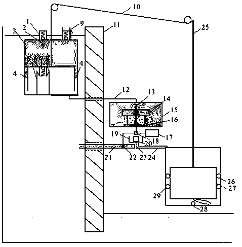
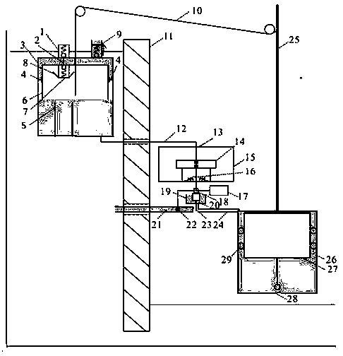
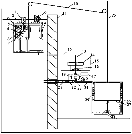
[0025] With reference to each figure, a float type composite power plunger device, said device includes a lifting mechanism capable of lifting infusion, a lifting mechanism for lifting, and a gas-liquid displacement work mechanism that provides power for the lifting mechanism and the lifting mechanism; The lifting part of the lifting mechanism is connected with the lifting part of the lifting mechanism through a power transmission chain; The buoyancy powers the lifting mechanism and the lifting mechanism; the lifting mechanism is placed in the high water zone and the lifting mechanism is located above the low water zone.

[0026] The lifting mechanism includes a pump body 3 and a plunger 6, the plunger 6 is located in the pump body 3, and the ring cavity between the plunger 6 and the pump body 3 is provided with a sealing baffle 4 for sealing fit, and the sealing baffle 4 is fixed On the inner wall of the pump body 1; the top of the plunger 6 is provided with a plunger exhaust...


PUM


Abstract

The invention belongs to the technical field of energy-conservation and environment-friendly equipment and particularly relates to a float type composite powder plunger device. The float type composite powder plunger device comprises a hoisting mechanism capable of achieving lifting liquid conveying, a lifting mechanism used for hoisting and a gas-liquid replacement acting mechanism providing powder for the hoisting mechanism and the lifting mechanism. The upward hoisting part of the hoisting mechanism is connected with the upward lifting part of the lifting mechanism through a power transmission chain. The gas-liquid replacement acting mechanism is connected with the hoisting mechanism and the lifting mechanism through gas exchange systems correspondingly. Floating force generated in thegas-liquid replacement process is used for providing power for the hoisting mechanism and the lifting mechanism. The hoisting mechanism is arranged in a high-water-level area, and the lifting mechanism is located above a low-water-level area. The float type composite power plunger device is a combination body of a float and a plunger, liquid conveying is achieved through the gas-liquid replacementacting mechanism and the water level difference, a large amount of energy does not need to be consumed in the liquid conveying process, and only an extremely small part of electric energy is needed for providing electricity for an electrical element. Structural design is reasonable, energy conservation and environment friendliness are achieved, and the device can be easily used and popularized ina large scale.

Description

Technical field: [0001] The invention belongs to the technical field of energy-saving and environment-friendly equipment, and in particular relates to a float type composite power plunger device. Background technique: [0002] Piston pumps require high-precision sealing. Everything attached to it, including sealing surfaces, check valves, outlet pipes, etc., all generate movement resistance and consume a lot of energy. Driving the plunger pump consumes a lot of energy. A large amount of energy can be saved if a float-type upward floating force plunger is used. The plunger itself is a float, which moves upward together through buoyancy and mechanical force, and uses the water level difference (potential energy of water) and the buoyancy generated by gas-liquid displacement to perform lifting infusion, which will save a lot of energy. energy. Therefore, it is very necessary to design a float type composite power plunger device that can save a lot of energy. Invention conten...

Claims


Application Information

Patent Timeline
Patent Type & Authority Applications(China)
IPC IPC(8): F04B9/10F04B53/02F04B53/06F04B49/22
CPCF04B9/10F04B49/22F04B53/02F04B53/06
Inventor 梁也
Owner 梁也
Learn More