Device for assembling built-in rotor permanent magnets of permanent magnet motor with long iron core

A technology for permanent magnet motors and permanent magnets, which is applied in the field of assembling permanent magnets for built-in rotors of long iron core permanent magnet motors, and can solve problems such as high labor intensity for assembly operators, failure to ensure assembly accuracy, and easy breakage of permanent magnets. Achieve the effects of simple structure, low cost and reduced labor intensity

Pending Publication Date: 2020-02-14
SHANGHAI MARINE EQUIP RES INST
View PDF0 Cites 3 Cited by
  • Summary
  • Abstract
  • Description
  • Claims
  • Application Information

AI Technical Summary

Problems solved by technology

[0002] When assembling the permanent magnet of the built-in rotor of the long-core permanent magnet motor, the existing method of manually holding the magnetic steel for assembly cannot guarantee the accuracy of the assembly when assembling the permanent magnet far from the assembly end, and there are also problems. Bigger security risk
At the same time, the magnetic steel used in large and medium-sized high-speed permanent magnet motors is relatively large, and the magnetic force between the permanent magnet and the permanent magnet and the ferromagnetic material is relatively large. The permanent magnet is easily broken during assembly, and the labor intensity of the assembly operator is relatively high. It is necessary to specially design the permanent magnet assembly device for the built-in rotor of long iron core permanent magnet motors to ensure accurate, safe and efficient assembly of permanent magnets

Method used


Image

  • Device for assembling built-in rotor permanent magnets of permanent magnet motor with long iron core
  • Device for assembling built-in rotor permanent magnets of permanent magnet motor with long iron core
  • Device for assembling built-in rotor permanent magnets of permanent magnet motor with long iron core

Examples


Embodiment Construction

[0023] The present invention will be further described below in conjunction with the accompanying drawings and embodiments.

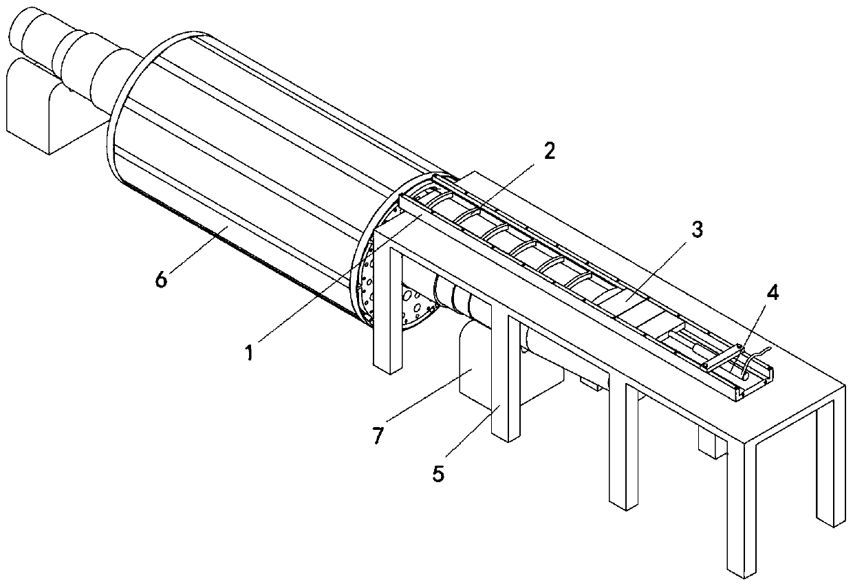
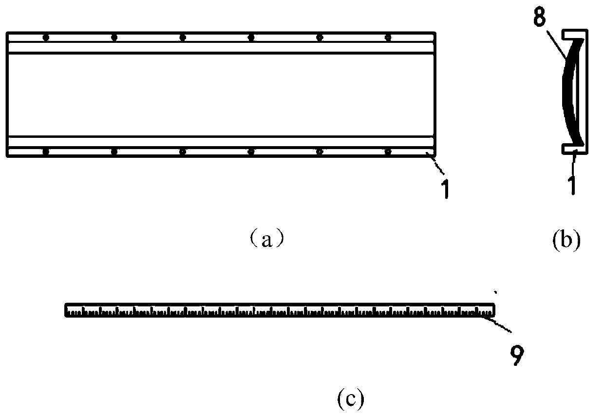
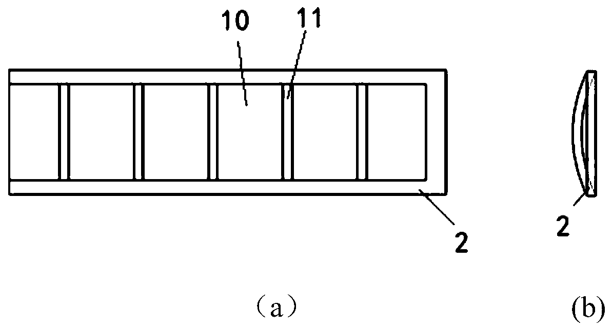
[0024] Such as figure 1 , 2 , 3, a device for assembling the built-in rotor permanent magnet of a long iron-core permanent magnet motor, comprising a permanent magnet tooling groove 1, a push plate 2, a top block 3, an oil pressure cylinder 4 and a wooden support 5, the push plate 2 and the permanent magnet The magnet tooling groove 1 is connected by sliding, the hydraulic cylinder 4 is fixedly connected with the top block 3; the top block 3 is connected with the push plate 2; the permanent magnet tooling groove 1 is installed on the assembly end surface of the rotor 6; the whole device is placed on the wooden support 5 . Wherein, the permanent magnet tooling groove 1 and the push plate 2 are non-magnetic materials.

[0025] When assembling the permanent magnet 8, first place the shafts at both ends of the rotor 6 on the V-shaped pad 7 respectively, ...


PUM


Abstract

The invention relates to a device for assembling built-in rotor permanent magnets of a permanent magnet motor with a long iron core. The device comprises a permanent magnet tool groove, a push plate,an ejector block, an oil hydraulic cylinder and a wooden support. The permanent magnet tool groove is formed in the wooden support. The front end of the permanent magnet tool groove is arranged on anassembling end face of a rotor. The push plate is arranged in the permanent magnet tool groove, and is connected with the permanent magnet tool groove in a sliding manner. The rear end of the push plate is in contact connection with the front end of an ejector block arranged in the permanent magnet tool groove, the rear end of the ejector block is connected with the oil hydraulic cylinder, and theoil hydraulic cylinder drives the push plate through the ejector block to push permanent magnets placed in the front portion of the permanent magnet tool groove into an iron core of the rotor along the permanent magnet tool groove. The push plate is pushed through the oil hydraulic cylinder to install the permanent magnets, repulsive force between the permanent magnets is easily overcome, and whole assembly is achieved. Because of the permanent magnet tool groove, the permanent magnets can be conveniently stored and directionally pushed, and a guiding effect on assembly of the permanent magnets is achieved.

Description

technical field [0001] The invention relates to an assembly device, in particular to a device for assembling a permanent magnet of a built-in rotor of a long iron core permanent magnet motor. Background technique [0002] When assembling the permanent magnet of the built-in rotor of the long-core permanent magnet motor, the existing method of manually holding the magnetic steel for assembly cannot guarantee the accuracy of the assembly when assembling the permanent magnet far from the assembly end, and there are also problems. greater safety hazard. At the same time, the magnetic steel used in large and medium-sized high-speed permanent magnet motors is relatively large, and the magnetic force between the permanent magnet and the permanent magnet and the ferromagnetic material is relatively large. The permanent magnet is easily broken during assembly, and the labor intensity of the assembly operator is relatively high. It is necessary to specially design the permanent magne...

Claims


Application Information

Patent Timeline
Patent Type & Authority Applications(China)
IPC IPC(8): H02K15/03
CPCH02K15/03
Inventor 张家玉杨智陈琳李姗蒋山赵泰然
Owner SHANGHAI MARINE EQUIP RES INST
Why Eureka
Try Eureka