Pulmonary artery dilatation forceps
A technique of dilating forceps and pulmonary artery, applied in the medical field, can solve the problems of time-consuming, prolong the overall time of cardiopulmonary bypass, and cannot be quantified in the first time, and achieve the effect of simple operation, shortening operation time, and reducing complications.
- Summary
- Abstract
- Description
- Claims
- Application Information
AI Technical Summary
Problems solved by technology
Method used
Image

Examples
Embodiment 1
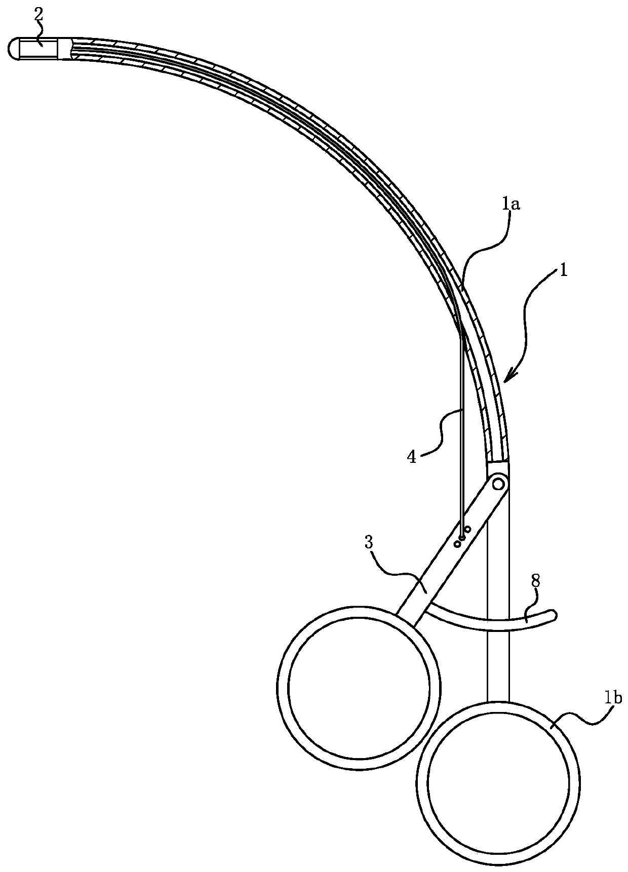
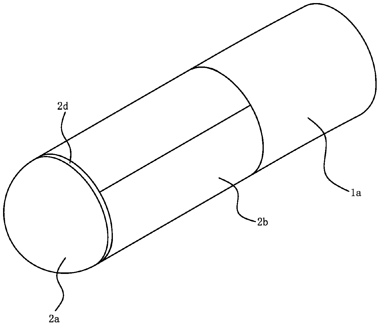
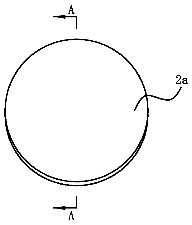
[0018] Example 1: as Figure 1 to Figure 5 As shown, a pulmonary artery dilation forceps includes a forceps handle 1, a forceps head 2 and a manipulation piece.
[0019] The pliers handle 1 includes a tubular base tube 1a and a holding member 1b fixedly connected to one end of the base tube 1a, and the drawings in the description show that the holding member 1b is a finger ring. The base pipe 1a has an arc shape, preferably the base pipe 1a has a circular arc shape and a length of 1 / 4 to 1 / 3 of the entire circumference. The operating member is connected with one end of the base pipe 1a, and a rope-shaped transmission member is pierced through the base pipe 1a. connect. The drawings in the description show that the operating member is trigger 3 and the transmission member is cable 4; The trigger 3 is fixed with a positioning fin 8, the positioning fin 8 has a first positioning tooth arranged continuously, and the base pipe 1a has a second positioning tooth meshing with the f...
Embodiment 2
[0027] Example 2: as Image 6 As shown, the structure and principle of this embodiment are basically the same as those of the first embodiment, and the basic similarities will not be described redundantly, only the differences will be described.
[0028] The operating member is a crank, the transmission member is a flexible transmission shaft 6, the crank is rotatably connected with the base pipe 1a, and one end of the transmission member is connected with the crank.
[0029] The guide seat 2a is a split structure, and the guide seat 2a includes a hemispherical head 2a2, a connecting seat 2a3 and a plurality of guide rod portions 2a1. The connection seat 2a3 is annular, and the connection seat 2a3 is connected with the other end face of the base pipe 1a by a screw thread. The connecting seat 2a3 and the hemispherical head 2a2 are coaxially arranged, and multiple expansion flaps 2b are arranged circumferentially along the axis of the hemispherical head 2a2. One end of the gui...
Embodiment 3
[0032] Example three: as Figure 7 As shown, the structure and principle of this embodiment are basically the same as those of the first embodiment, the basic similarities will not be described redundantly, and only the different places will be described. The lobe 2b can attract the permanent magnet 9 or the expansion lobe 2b is fixed with an iron piece that can attract the permanent magnet 9 . The expansion valve 2b attracts with the permanent magnet 9, which improves the uniformity of the force of the expansion valve 2b, improves the restoring force of the expansion valve 2b, and ensures that the expansion valve 2b can be reset in place.
PUM
 Abstract
Description
Claims
Application Information
 - R&D Engineer
- R&D Manager
- IP Professional
- Industry Leading Data Capabilities
- Powerful AI technology
- Patent DNA Extraction
Browse by: Latest US Patents, China's latest patents, Technical Efficacy Thesaurus, Application Domain, Technology Topic.
© 2024 PatSnap. All rights reserved.Legal|Privacy policy|Modern Slavery Act Transparency Statement|Sitemap