
Novel chemical production device

A new type of chemical production technology, applied in feeding devices, chemical instruments and methods, chemical/physical processes, etc., can solve problems such as low production efficiency and slow reaction speed, and achieve improved production efficiency, block reaction speed, increase The effect of crushing efficiency

Inactive Publication Date: 2020-02-18
LEIYANG JINYUE SCI & TECH DEV
View PDF7 Cites 0 Cited by
  • Summary
  • Abstract
  • Description
  • Claims
  • Application Information

AI Technical Summary

Problems solved by technology

The above-mentioned patents have the following disadvantages: the chemical production device directly puts raw materials into the stirring mechanism for stirring, the reaction speed is slow, and the production efficiency is low

Method used


Image

  • Novel chemical production device
  • Novel chemical production device
  • Novel chemical production device

Examples


Embodiment 1

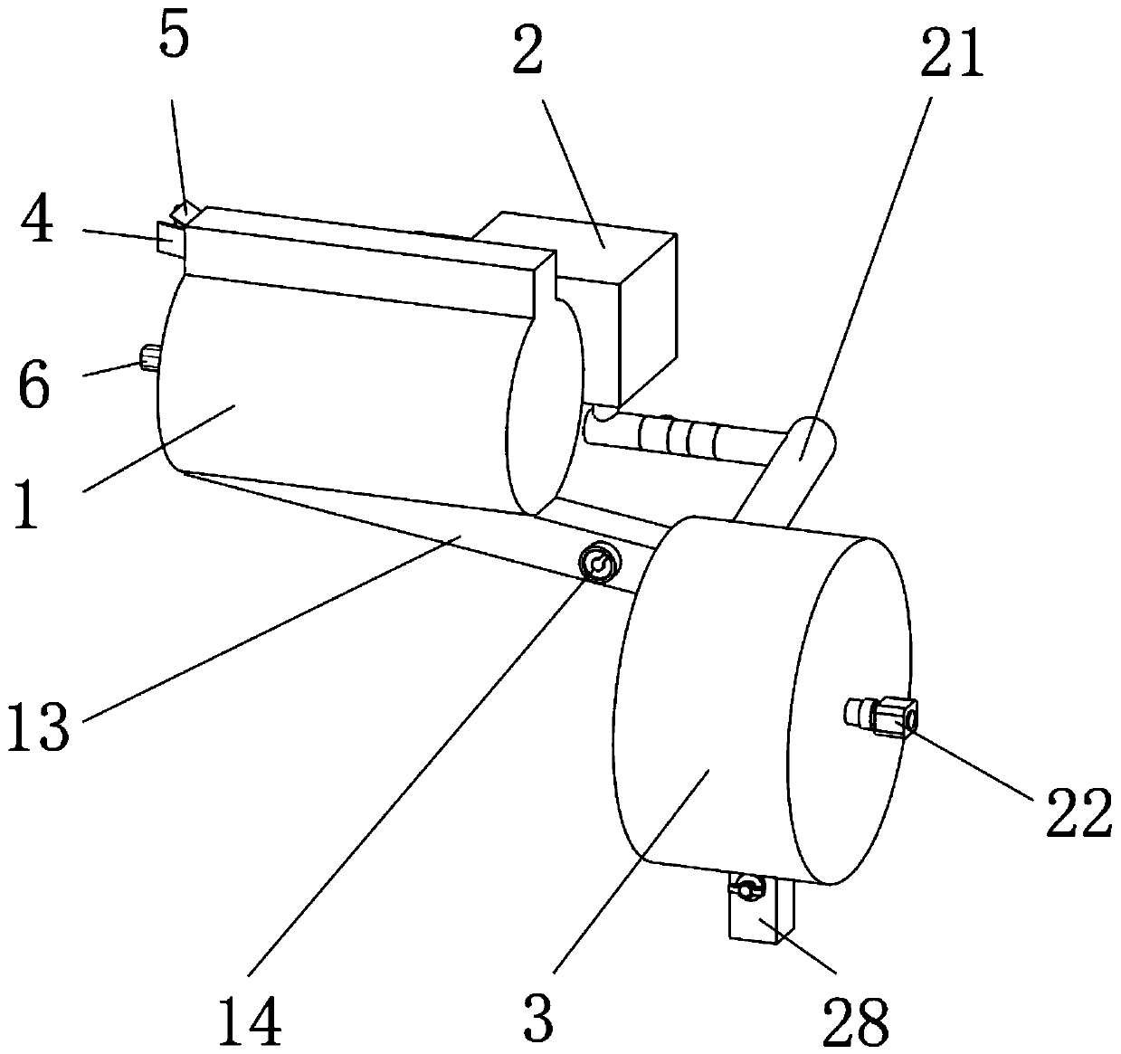
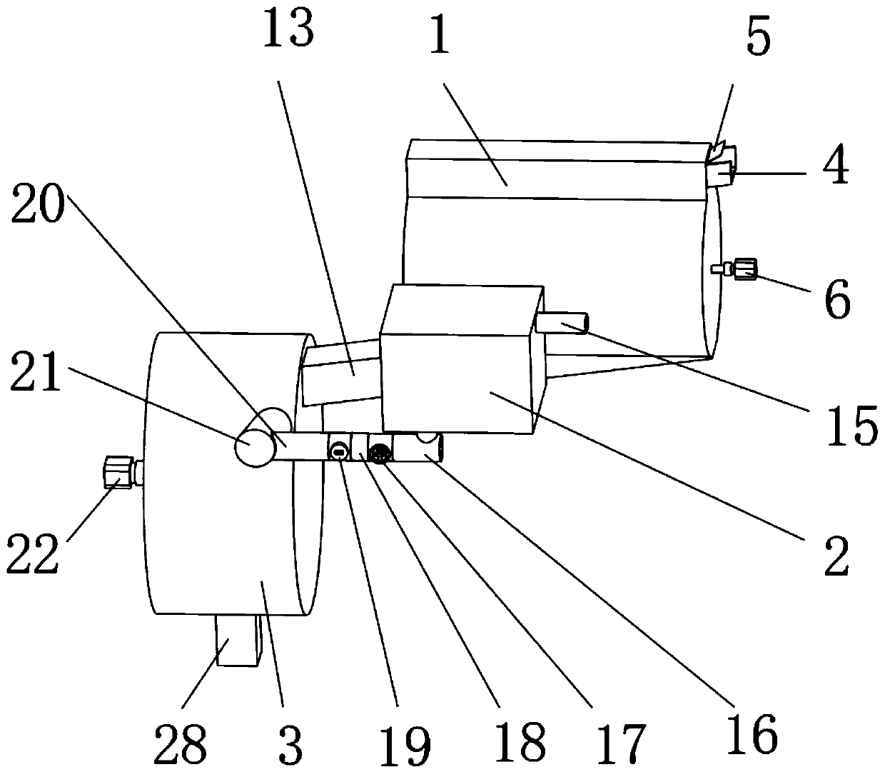
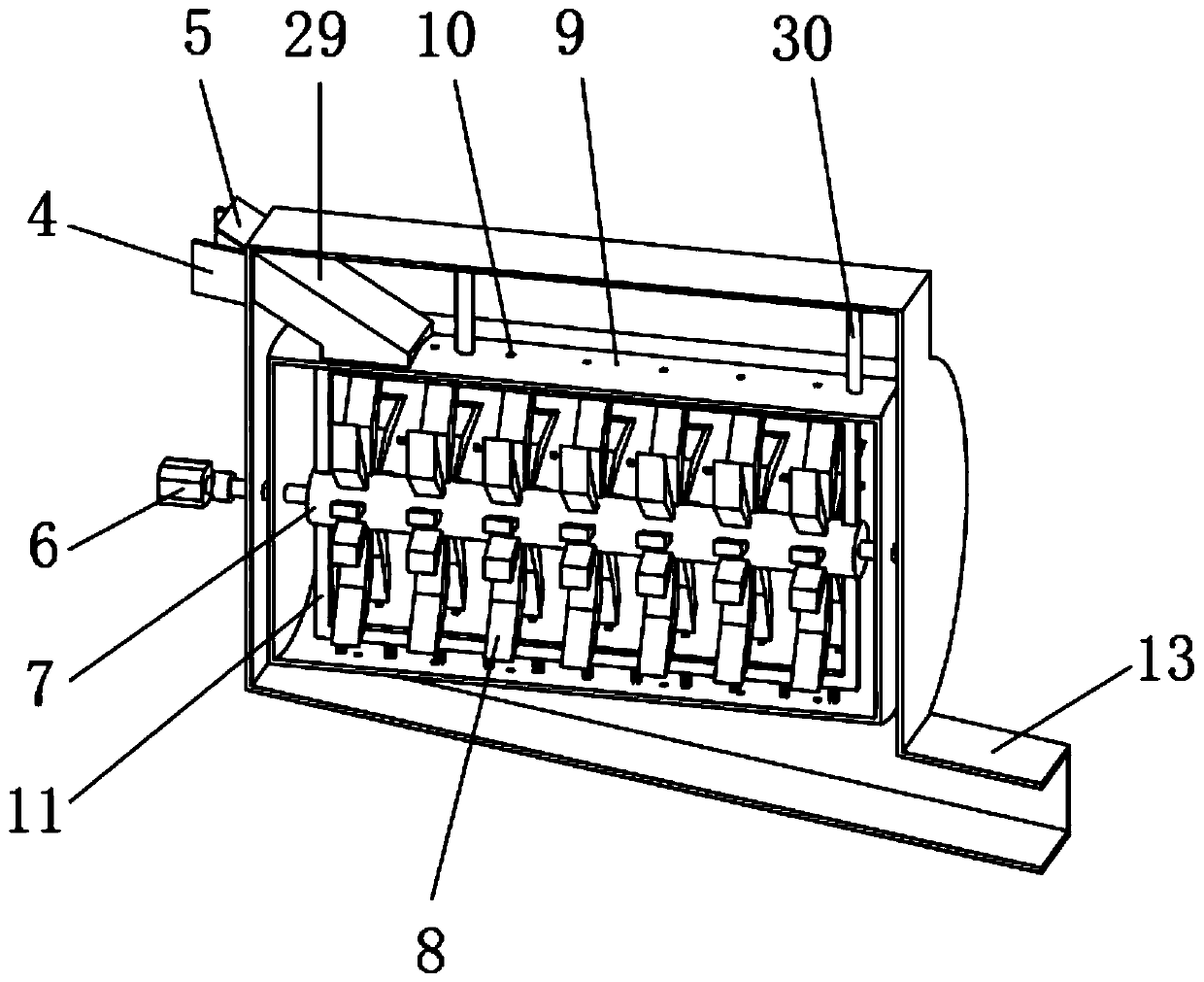
[0033] A new type of chemical production device, such as figure 1 , image 3 As shown, it includes a solid chamber 1 and a liquid chamber 2, the outer wall of the solid chamber 1 is welded with a solid feed port 4, and the outer wall of the solid chamber 1 is connected with a feed gate 5 through a shaft and a bearing. A feed pipe 29 is welded on the inner wall of one side of the chamber 1, and a crushing box 9 is welded on the outer wall of one side of the feed pipe 29. When the solid feed port 4 is put into the material, it can be discharged through the feed pipe 29 to the inside of the crushing box 9. , the top outer wall of the crushing box 9 is welded with a support column 30, the support column 30 is welded to the top inner wall of the solid chamber 1, and the outer wall of one side of the solid chamber 1 is equipped with a crushing motor 6 through the first motor seat, and the crushing box 9 The inner walls of both sides are equipped with the same crushing main shaft 7 ...

Embodiment 2

[0044] A new type of chemical production device, such as Figure 4 As shown, in order to solve the problem of imprecise crushing; this embodiment makes the following improvements on the basis of embodiment 1: the outer wall of the crushing main shaft 7 is welded with a brush head frame 11, and the outer walls of both sides of the brush head frame 11 pass through the brush head holder Evenly distributed brush heads 12 are installed. When the crushing main shaft 7 rotates, it can drive the brush head frame 11 to rotate, and then drive the brush head 12 to work. By setting the brush head frame 11 and the brush head 12, the crushing teeth 8 can be crushed while The brushing and stripping of the solid materials stuck to the inner wall of the crushing box 9 and the cleaning of the large particles accumulated in the sieve holes 10 effectively increase the crushing efficiency and avoid the blockage of the sieve holes 10 at the same time.

[0045] When the present embodiment is in use,...


PUM


Abstract

The invention discloses a novel chemical production device, relates to the technical field of chemical production devices, and aims to solve that problem of low production efficiency; the novel chemical production device specifically comprises a solid chamber and a liquid chamber, wherein a solid feed inlet is welded on the outer wall at one side of the solid chamber; a feed door is connected withthe outer wall at one side of the solid chamber through a shaft and a bearing; a material guide pipe is welded on the inner wall at one side of the solid chamber; and a crushing box is welded on theouter wall at one side of the material guide pipe. By arrange sieve holes, small particle material entering the crushing box and small particle materials generated in the crushing process can be sieved through the sieve holes, convenience is provided for subsequent production; by setting a feeding switch, the staff can feed or stop solid materials according to the actual situation, convenience isprovided for production, and safety is enhanced at the same time. By setting a regulating valve, workers can adjust the rate of liquid raw materials flowing through the regulating valve according to the actual situation, thus realizing the controllability of liquid supply.

Description

technical field [0001] The invention relates to the technical field of chemical production equipment, in particular to a novel chemical production equipment. Background technique [0002] With the development of science and technology, the chemical industry has gradually developed into a multi-industry and multi-variety production department from the initial production of only a few inorganic products such as soda ash and sulfuric acid, and the organic products that mainly extract alizarin from plants to make dyes. The chemical industry is constantly progressing, and people's requirements for production efficiency are getting higher and higher. [0003] After retrieval, the Chinese patent application number is CN201820265147.7, which discloses a new type of chemical production device, including the main body of the chemical production device, a partition and a stirring mechanism. The partition is fixedly connected to the bottom of the inner wall of the main body of the chemi...

Claims


Application Information

Patent Timeline
Patent Type & Authority Applications(China)
IPC IPC(8): B01J19/18B01J19/00B01J4/00B02C18/14B02C18/22B02C23/16B08B1/00B08B1/04
CPCB01J19/18B01J19/0066B01J4/001B02C18/145B02C18/2291B02C23/16B02C2023/165B08B1/12B08B1/32
Inventor 周新红李泽龙义训坤黄涛
Owner LEIYANG JINYUE SCI & TECH DEV
Learn More