Exhaust pipe surface heat resisting treatment device and operation method thereof

A technology for heat treatment devices and exhaust pipes, applied in spraying devices, paint spray booths, etc., can solve problems such as uneven heat resistance on the surface, uneven painting of exhaust pipes, waste of resources, etc.

Active Publication Date: 2020-02-18
柳州市宏华机械有限公司 +1
View PDF10 Cites 5 Cited by
  • Summary
  • Abstract
  • Description
  • Claims
  • Application Information

AI Technical Summary

Problems solved by technology

[0004] The object of the present invention is to provide a heat-resistant treatment device for the surface of the exhaust pipe and its operation method. As a result, the heat resistance after painting is poor, and the heat resistance of the surface is uneven; at the same time, special fixtures are needed to fix the exhaust pipe during the clamping process, and at the same time, it is necessary to ensure that the fixture does not align the exhaust pipe during the painting process. Cause occlusion and avoid uneven spraying of the exhaust pipe; the process of painting with the existing heat-resistant treatment device for the surface of the exhaust pipe will produce a large amount of paint that is not attached to the surface of the exhaust pipe, which cannot be collected and recycled, resulting in a waste of resources technical issues

Method used


Image

  • Exhaust pipe surface heat resisting treatment device and operation method thereof
  • Exhaust pipe surface heat resisting treatment device and operation method thereof
  • Exhaust pipe surface heat resisting treatment device and operation method thereof

Examples


Embodiment Construction

[0037] The technical solutions of the present invention will be clearly and completely described below in conjunction with the embodiments. Apparently, the described embodiments are only some of the embodiments of the present invention, not all of them. Based on the embodiments of the present invention, all other embodiments obtained by persons of ordinary skill in the art without creative efforts fall within the protection scope of the present invention.

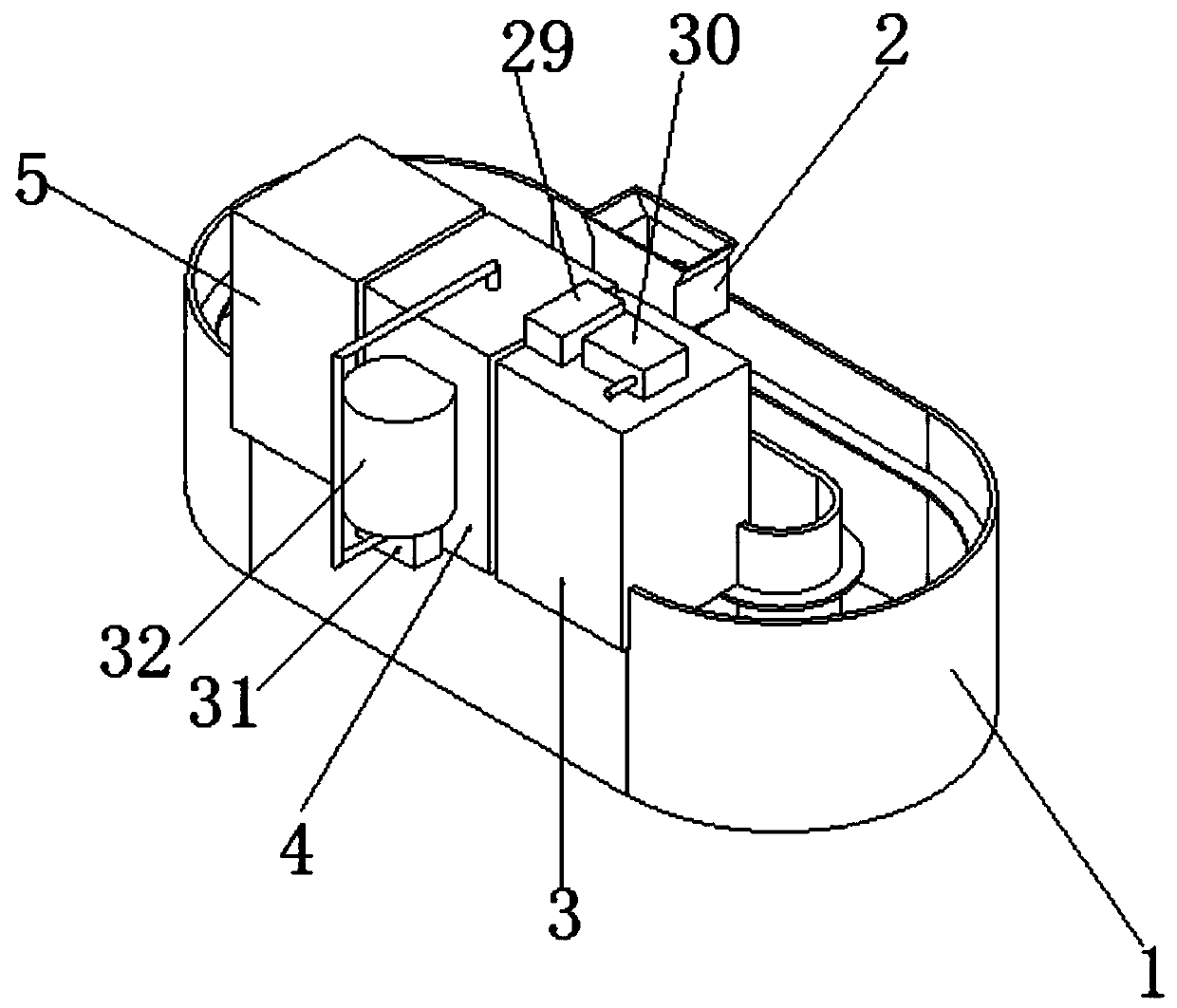
[0038] see Figure 1-8 As shown, an exhaust pipe surface heat-resistant treatment device includes an endless conveyor belt 1, a clamping mechanism 2, a cleaning box 3, a paint spraying box 4, and a drying box 5. Several clamping mechanisms 2 are installed inside the endless conveyor belt 1, A cleaning box 3, a painting box 4 and a drying box 5 are sequentially installed on one side of the top of the endless conveyor belt 1;

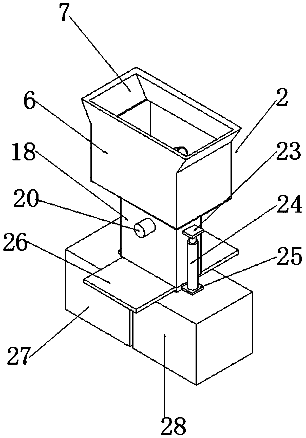
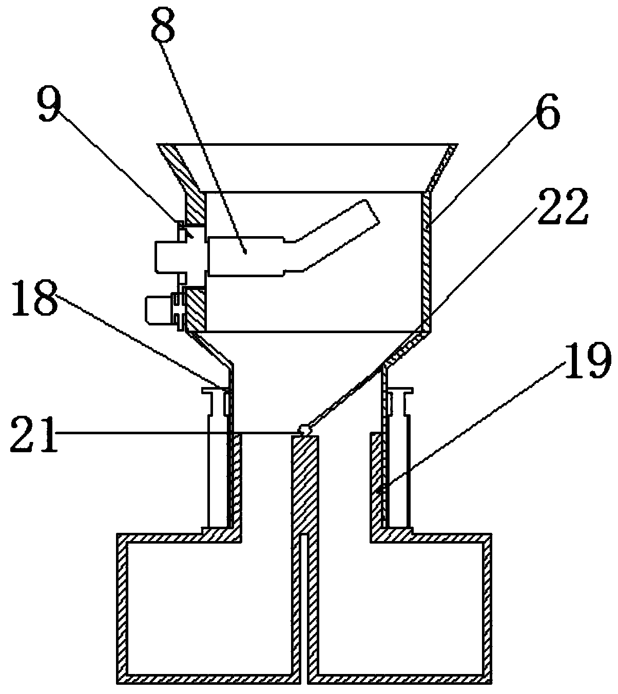
[0039] The clamping mechanism 2 includes a tooling box 6, an expansion box side 7, an exhaust pipe...


PUM


Abstract

The invention discloses an exhaust pipe surface heat resisting treatment device which comprises a ring-shaped conveying belt, clamping mechanisms, a cleaning box, a paint spraying box and a drying box. The multiple clamping mechanisms are installed in the ring-shaped conveying belt. The cleaning box, the paint spraying box and the drying box are sequentially installed on one side of the top of thering-shaped conveying belt. By means of the exhaust pipe surface heat resisting treatment device, 360-degree cleaning is conducted on a rotating exhaust pipe in the cleaning box, it is ensured that the exhaust pipe is cleaned thoroughly, meanwhile, water obtained after cleaning is collected, and resources are saved; the exhaust pipe is blown through hot air after cleaning, it is ensured that no water spots are attached to the surface of the exhaust pipe, and subsequent paint spraying treatment is ensured; 360-degree cleaning is conducted on the rotating exhaust pipe in the paint spraying box,and it is ensured that paint spraying of the outer side of the exhaust pipe is uniform; and the clamping mechanisms are used for clamping the inner pipe wall of the exhaust pipe, shielding cannot becaused in the paint spraying process, meanwhile, surplus inorganic silicon high temperature resisting paint is collected, cyclic use is facilitated, and resources are saved.

Description

technical field [0001] The invention relates to the field of exhaust pipe processing equipment, in particular to an exhaust pipe surface heat-resistant treatment device and an operating method thereof. Background technique [0002] There are two methods of heat-resistant treatment on the surface of the exhaust pipe. One is to use coating technology on the metal surface, such as electroplating, chemical plating and spray painting on the metal surface, and the other is to change the specific performance of the metal surface. It can be realized by changing the specific structure and performance, and the exhaust pipe surface heat-resistant treatment device of the present invention performs heat-resistant treatment on the exhaust pipe surface by spraying paint. [0003] In the existing heat-resistant treatment of the exhaust pipe by spraying paint, the surface of the exhaust pipe will have poor heat-resistant effect after painting due to the attached impurities, and the surface h...

Claims


Application Information

Patent Timeline
Patent Type & Authority Applications(China)
IPC IPC(8): B05B13/02B05B14/00B05B16/20B05B16/40
CPCB05B13/0242B05B14/00B05B16/20B05B16/40
Inventor 廖贵成张俊蓝雄张景孟黄力何柏灵
Owner 柳州市宏华机械有限公司
Why Eureka
Try Eureka