A kind of airflow dispensing equipment and dispensing method for electronic processing

An air flow and dispensing technology, which is applied in the direction of cleaning methods, cleaning methods and utensils, chemical instruments and methods using gas flow, and can solve the problems of accelerating the efficiency and quality of workpiece dispensing

Active Publication Date: 2021-04-20
XUZHOU FLY DREAM ELECTRONICS & TECH
View PDF8 Cites 0 Cited by
  • Summary
  • Abstract
  • Description
  • Claims
  • Application Information

AI Technical Summary

Problems solved by technology

[0006] Aiming at the problems existing in the prior art, the object of the present invention is to provide an airflow dispensing device for electronic processing and a dispensing method thereof, which can change the way of dispensing glue and replace it with a shorter dispensing needle to play The role of the initial guide, through the optimization of the structure on the inner variable air cylinder, the circular airflow of the laminating glue is produced, and it is injected synchronously with the heating. On the one hand, the glue coming out of the needle is protected and kept warm, and on the other hand, the surface of the workpiece is blown. Clean operation, at the same time, use the circumferential dispersion of the annular airflow after encountering obstacles to uniformly heat the surface of the workpiece, forcing the contact surface between the glue and the workpiece to solidify and bond in advance to prevent flow off, and improve the positioning effect and accuracy of dispensing. Improve the needle clogging and dispensing quality problems that often occur in traditional dispensing, start from the temperature control throughout the dispensing process, from filling to curing in one go, not easy to be interrupted, and there are no redundant processing steps, greatly speeding up the dispensing of workpieces Glue Efficiency and Quality

Method used


Image

  • A kind of airflow dispensing equipment and dispensing method for electronic processing
  • A kind of airflow dispensing equipment and dispensing method for electronic processing
  • A kind of airflow dispensing equipment and dispensing method for electronic processing

Examples


Embodiment 1

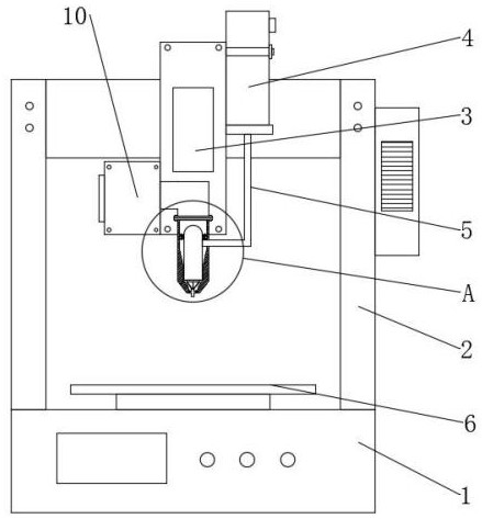
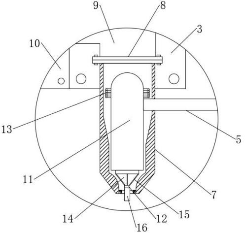
[0048] see Figure 1-2 , an air-flow dispensing device for electronic processing, including a dispensing workbench 1, a mobile support 2 is installed on the upper end of the dispensing workbench 1, most of the mobile support 2 can be designed as a three-axis motion mechanism at present, and the specific structure and function are in This will not go into details here, the mobile bracket 2 is equipped with a mounting plate 3, the upper end of the dispensing workbench 1 is fixedly connected with a receiving plate 6, the front end of the mounting plate 3 is fixedly connected with an inner changing air duct 7, and the inner side of the inner changing air duct 7 is provided. Dispensing head 11, the dispensing head 11 is an existing technology, the dispensing process can be automatically realized by setting parameters, the dispensing head 11 is connected with the glue replenishing hard tube 5, and the glue replenishing hard tube 5 runs through the inside and changes out of the air cy...


PUM


Abstract

The invention discloses an air-flow dispensing device for electronic processing and a dispensing method thereof, belonging to the technical field of electronic processing, which can realize changing the dispensing mode and replace it with a shorter dispensing needle to play the role of initial guidance. The structure optimization on the inner variable air duct creates a ring-shaped airflow for laminating the glue, and it is ejected synchronously after heating. On the one hand, the glue coming out of the needle is protected and kept warm, and on the other hand, the surface of the workpiece is blown clean. At the same time, the circular airflow is used to The circumferential dispersion of the airflow after encountering obstacles can uniformly heat the surface of the workpiece, forcing the contact surface between the glue and the workpiece to solidify and bond in advance to prevent flow off, improve the positioning effect and accuracy of dispensing, and improve the traditional dispensing. Needle clogging and dispensing quality problems can be controlled from temperature throughout the entire dispensing process, from filling to curing in one go without interruption, and there are no redundant processing steps, which greatly speeds up the dispensing efficiency and quality of workpieces.

Description

technical field [0001] The invention relates to the technical field of electronic processing, and more specifically relates to an air-flow dispensing device for electronic processing and a dispensing method thereof. Background technique [0002] In the production process of various electronic devices or circuit boards, a glue dispenser is often used. The glue dispenser is also called a glue applicator, a glue dispenser or a glue pouring machine, etc., to control the fluid. An automatic machine that drips and coats the fluid on the surface of the product or inside the product, which can realize three-dimensional and four-dimensional path dispensing, with the advantages of precise positioning, precise glue pulling and no wire drawing. Its working principle is: the glue is stored in the glue storage room formed by the rubber cylinder and the piston, the glue storage room is connected with the dispensing nozzle through the feeding pipe, and a valve is set at the connection betwe...

Claims


Application Information

Patent Timeline
Patent Type & Authority Patents(China)
IPC IPC(8): B05C5/02B05C5/00B05C13/00B08B5/02B05C9/14B05D3/04B05D1/26
CPCB05C5/001B05C5/0208B05C9/14B05C13/00B05D1/26B05D3/0413B08B5/02
Inventor 程义
Owner XUZHOU FLY DREAM ELECTRONICS & TECH
Why Eureka
Try Eureka