Magnetic collecting device for improving uniformity of deformation of pipe fitting and electromagnetic forming device of magnetic collecting device

A magnetic collector and uniformity technology, applied in the field of material processing and forming, can solve the problems of uneven deformation of pipe fittings, uneven deformation of pipe fittings or flat plates, etc., and achieve the effects of improving service life, easy operation, and ensuring uniformity

Pending Publication Date: 2020-02-18
CENT SOUTH UNIV
View PDF12 Cites 8 Cited by
  • Summary
  • Abstract
  • Description
  • Claims
  • Application Information

AI Technical Summary

Problems solved by technology

[0004] However, in the literature "Research on the Electromagnetic Pulse Connection Characteristics of Aluminum Alloy and Steel Pipe Fittings" and "Simulation of the Working Principle and Improvement of the Electromagnetic Forming Magnet Collector for Sheet Metal", the author found that the pipe fittings or sheet metal corresponding to the gap of the magnet collector The magnetic field force is smaller than other areas of the tube or sheet, which eventually leads to uneven deformation of the tube or plate
For example, in the document "Research on Electromagnetic Pulse Connection Characteristics of Aluminum Alloy and Steel Pipe Fittings", Fan Wei found through experiments that the deformation of the pipe fittings under the action of the magnet collector is uneven

Method used


Image

  • Magnetic collecting device for improving uniformity of deformation of pipe fitting and electromagnetic forming device of magnetic collecting device
  • Magnetic collecting device for improving uniformity of deformation of pipe fitting and electromagnetic forming device of magnetic collecting device
  • Magnetic collecting device for improving uniformity of deformation of pipe fitting and electromagnetic forming device of magnetic collecting device

Examples


Embodiment 1

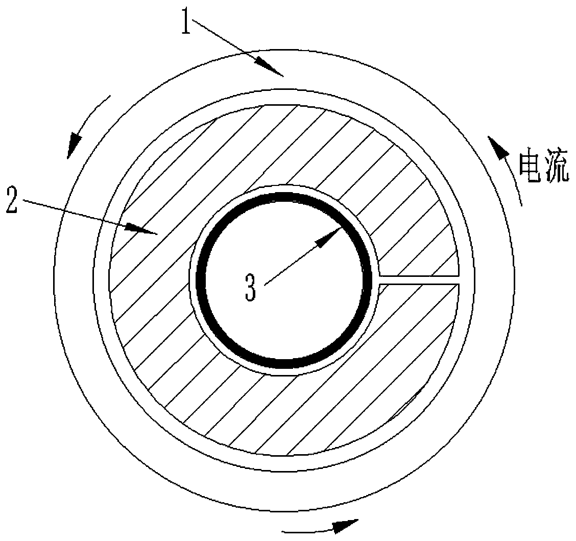
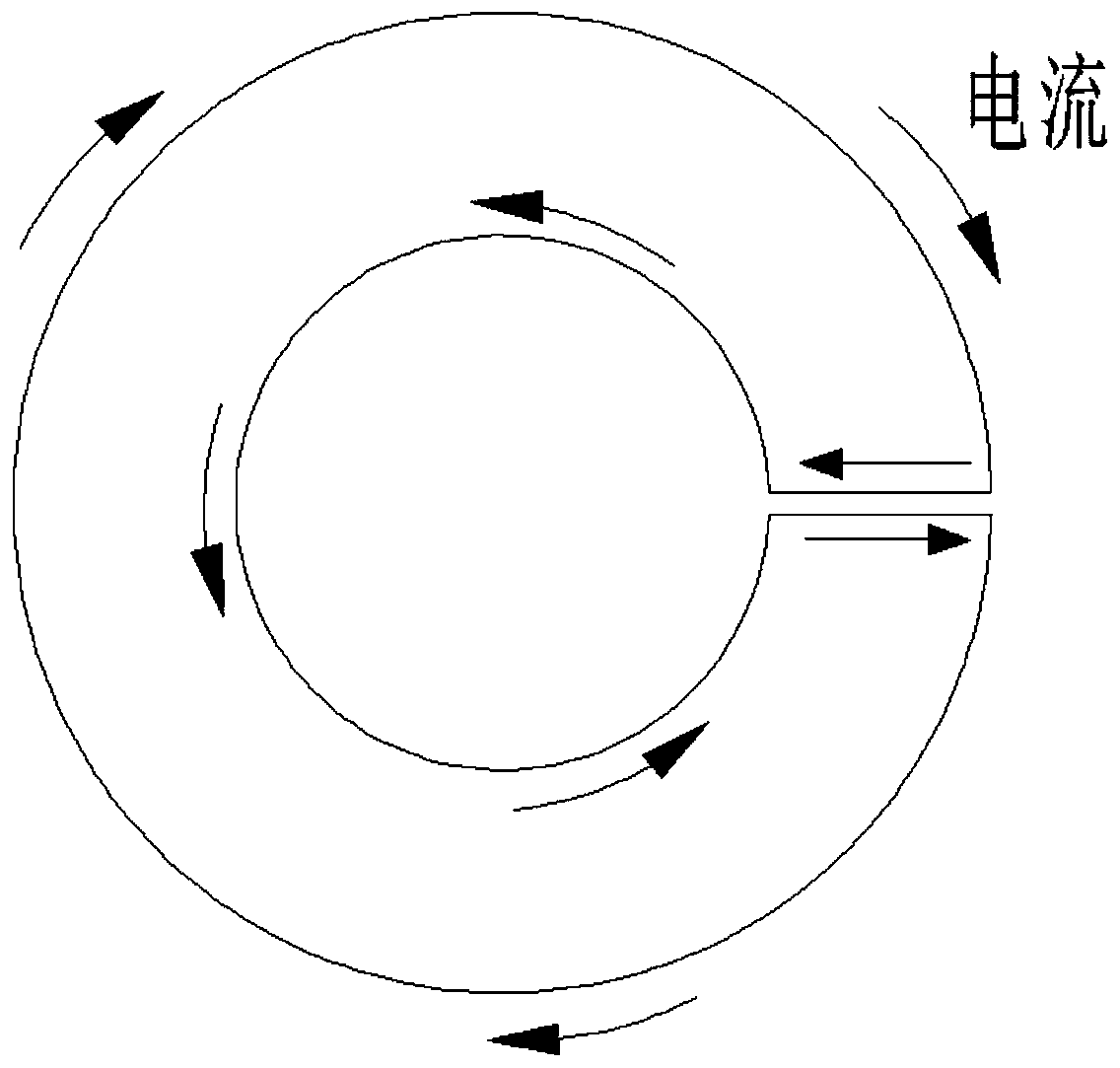
[0036] Such as Figure 4 As shown, the embodiment of the present invention discloses a magnetic collector for improving the uniformity of pipe deformation. The magnetic collector 2 is provided with a ring structure with a through hole 6 at the center, and the magnetic collector 2 is provided with a ring structure along the through hole 6. radially through the gap 4 of the side wall of the magnetic collector 2 (different from the attached Figure 1-3 The traditional single-slit magnetic collector shown), the magnetic collector 2 is located on the inner wall of the through hole 6 and is also provided with at least one slit 5, the slit 5 extends along the axial direction of the through hole 6, and the slit 5 and the gap 4 are along the through hole 6. The circumferential direction of the holes is evenly arranged. Therefore, when the magnetic collector 2 is designed with multiple slits 5 , the magnetic field force corresponding to the slits 5 is still smaller than the area corres...

Embodiment 2

[0040] In this example, if Figure 5-6 As shown, the magnetic collector 2 is a split structure, and the magnetic collector 2 includes a plurality of split magnetic collectors 21, and the plurality of split magnetic collectors 21 form a ring structure with a through hole 6 in the center, and the adjacent split magnetic collectors 21 A gap 4 is formed between them (at this time, it can also be regarded as the formation of other gaps 5 passing through the side wall of the integrated magnet collector 2), and the split magnet collector 21 and the gap 4 are symmetrically arranged along the center of the through hole 6 . In this embodiment, the magnetic collector 2 can be opened and closed conveniently, and the magnetic collector 2 can be easily moved to any area where the pipe fitting 3 is deformed, and is not affected by the length of the pipe fitting 3 and the variable section of the pipe fitting 3, making it easier to operate.

[0041]In specific setting, the width of any gap 4 ...

Embodiment 3

[0044] In this example, if Figure 7-8 As shown, the magnetic collector 2 is a split structure, and the magnetic collector 2 includes a plurality of split magnetic collectors 21, and the plurality of split magnetic collectors 21 form a ring structure with a through hole 6 in the center, and the adjacent split magnetic collectors 21 A gap 4 is formed between them, and the split magnet collector 21 is located on the inner wall of the through hole 6. At least one gap 5 is also provided. The gap 5 extends along the axial direction of the through hole 6, and the gap 5 and the gap 4 extend along the through hole. 6 are evenly arranged circumferentially. Similarly, for the convenience of processing, the slit 5 is a through-groove structure having the same width as the gap 4 and penetrating along the axial direction of the through-hole 6 .

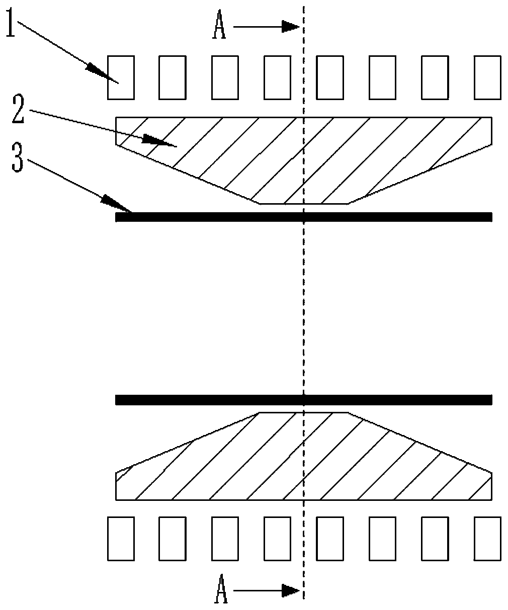
[0045] Then, the present invention discloses an electromagnetic forming device, which includes the magnetic collector for improving the uniformi...


PUM


Abstract

The invention discloses a magnetic collecting device for improving uniformity of deformation of a pipe fitting and an electromagnetic forming device of the magnetic collecting device. The magnetic collecting device is of an annular structure with a through hole formed in the center, a gap penetrating through the side wall of the magnetic collecting device in the radical direction of the through hole is formed in the magnetic collecting device, one or more seams are further formed in the inner wall, located in the through hole, of the magnetic collector, the seams extend in the axial directionof the through hole, and the seams and the gap are evenly arranged in the circumferential direction of the through hole. The magnetic collecting device is designed to be have multiple seams, the magnetic field force corresponding to the seams is still smaller than that of the area not corresponding to the seams, so that the material has a tendency to flow to the multiple seams. Although the magnetic field force on both sides of the seams is greater than the magnetic field force of the seams, material flow is continuous, the deformation of the material on both sides of the seams drives the deformation of the material of the seams, and thus uniformity of the overall deformation is ensured. Therefore, uniformity of material deformation can be greatly improved by the multi-seam magnetic collecting device.

Description

technical field [0001] The invention relates to the technical field of material processing and forming, in particular to a magnetic collector and an electromagnetic forming device for improving the deformation uniformity of pipe fittings. Background technique [0002] Magnet collector is a commonly used auxiliary part in electromagnetic pulse forming, and it is widely used in the forming of plate and tube parts. By changing the structure of the magnetic collector, the magnetic field generated by the coil can be concentrated in a small area of ​​the part to be deformed, so that the magnetic field in the local area of ​​space is greatly strengthened, and the purpose of improving the forming efficiency is achieved. [0003] For example: In the document "Study on Electromagnetic Pulse Connection Characteristics of Aluminum Alloy and Steel Pipe Fittings", Fan Wei used a pipe fitting magnet collector to realize the connection of aluminum pipe and steel pipe. In the literature "St...

Claims


Application Information

Patent Timeline
Patent Type & Authority Applications(China)
IPC IPC(8): B21D26/14
CPCB21D26/14
Inventor 崔晓辉颜子钦肖昂喻海良黄长清
Owner CENT SOUTH UNIV
Why Eureka
Try Eureka