
Annular punch

A technology of annular punch and annular groove, applied in the field of annular punch, can solve the problems of connection failure, inconvenience and high use cost, and achieve the effect of increasing the bonding area, avoiding leakage of aluminum water and improving the utilization rate.

Active Publication Date: 2020-02-18
重庆渝江压铸股份有限公司
View PDF9 Cites 0 Cited by
  • Summary
  • Abstract
  • Description
  • Claims
  • Application Information

AI Technical Summary

Problems solved by technology

[0005] Although the punch structure uses a beryllium-copper protective layer to reduce wear on the melting cup, it can be known from the published patent as a whole: 1. The beryllium-copper protective layer is essentially an integral punching head, and the overall production cost during specific production and processing Not low, because the beryllium copper protective layer wears quickly, although the melting cup is protected, the cost of use is still high; 2. Although the stamping head uses a circulating cooling chamber to cool the beryllium copper protective layer, the circulating cooling chamber and The contact surface of the beryllium copper protective layer is small, resulting in poor heat dissipation, so the heat dissipation problem of the beryllium copper protective layer has not been effectively improved; 3. The beryllium copper protective layer and the alloy steel punch body adopt a non-detachable connection method , that is, the beryllium-copper protective layer is wrapped on the outside of the alloy steel punch body and the two ends are limited and fixed by the cavity. Therefore, it is not only inconvenient to replace the beryllium-copper protective layer, but only destructive removal is required, and the installation also requires integral casting. Processing is troublesome; 4. The beryllium copper protective layer needs to be inserted into the melting cup in the axial direction, but if the outer dimension of the beryllium copper protective layer is too large, it cannot be inserted into the melting cup; If the gap between the inside of the cup is too large, it will cause leakage of aluminum water, etc., so that the beryllium copper protective layer is difficult to install and inconvenient to use; 5. If the beryllium copper protective layer and the alloy steel punch are threaded in the above structure, the The copper protective layer is in an intermittent high-temperature environment, which is affected by thermal expansion and contraction, which will lead to rotten teeth, which will cause thread deformation and connection failure

Method used


Image

  • Annular punch
  • Annular punch
  • Annular punch

Examples


Embodiment Construction

[0032] Below in conjunction with accompanying drawing and embodiment the present invention will be further described:

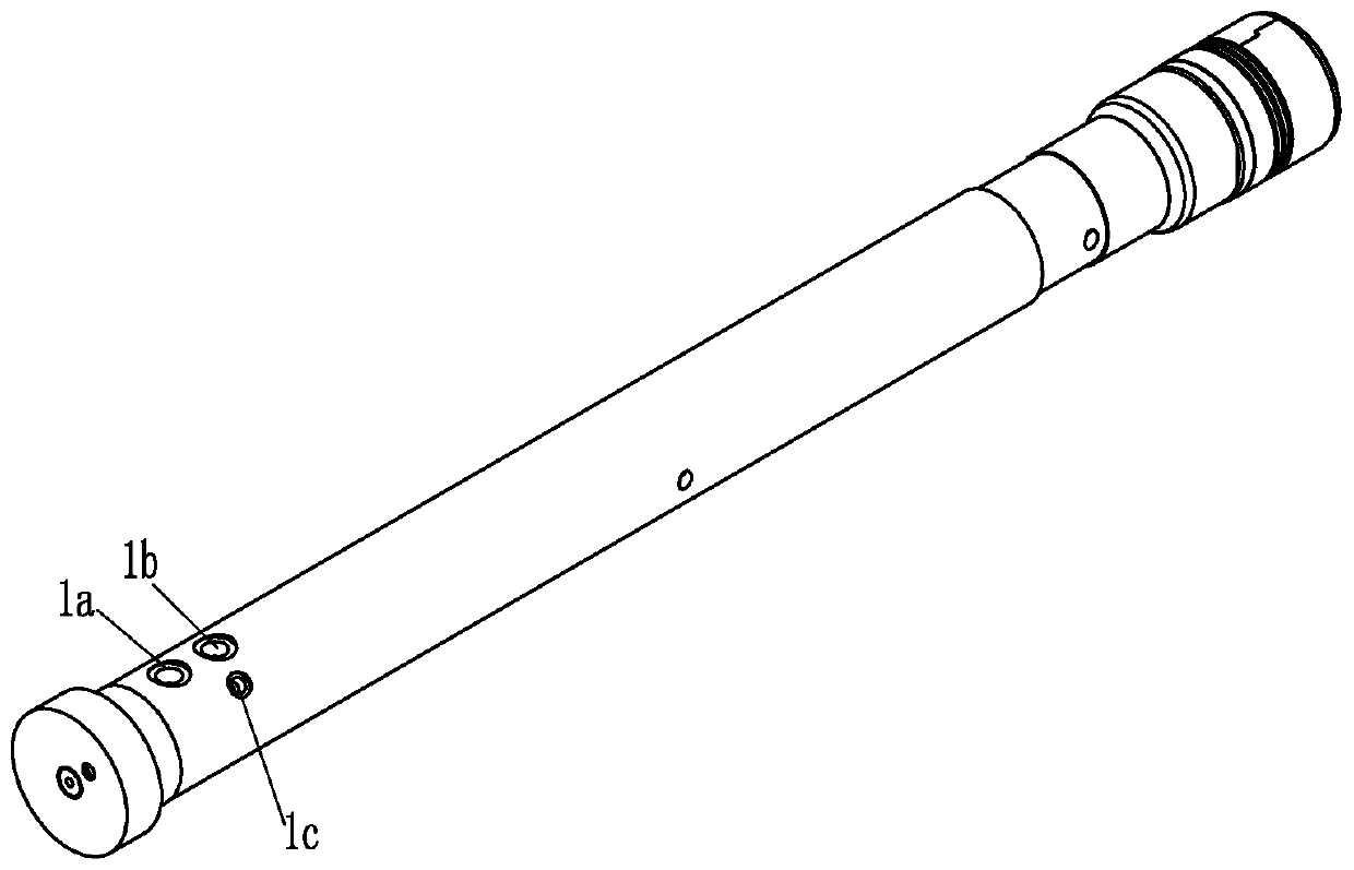
[0033] Such as figure 1, figure 2 , image 3 , Figure 4 , Figure 5 , Image 6 , Figure 7 , Figure 8 , Figure 9 with Figure 10 As shown, a ring punch disclosed by the present invention includes a lubricating rod 1 fixedly connected with a die-casting machine or an alloy steel punch body, and the lubricating rod 1, the support seat 2 and the plunger head 3 are made of cast iron, cast steel or alloy steel Made of material. The lubricating rod 1 can be fixedly connected with the die-casting machine directly, or can be fixed on the die-casting machine through the transition of the alloy steel punch body.

[0034] The lubricating rod 1 is coaxially provided with a first hollow cavity. The annular punch in this case also includes a support seat 2 and a plunger head 3, and both the support seat 2 and the plunger head 3 are coaxially fixed with the l...


PUM


Abstract

The invention discloses an annular punch. The annular punch comprises a lubricating rod, a supporting seat and a plunger head, wherein a connecting cavity is formed in the right end of the lubricatingrod, and the left end of the supporting seat is inserted into the connecting cavity and is in clearance fit with the inner wall of the connecting cavity; a circulating cooling cavity is formed between the end surface of a boss and an inner cavity of the plunger head, a left annular groove and a right annular groove are coaxially formed in the cavity wall of the circulating cooling cavity from left to right in sequence, a notch is formed in the outer wall of the boss, a two-section stepped hole is coaxially formed in the lubricating rod, a cooling pipe is coaxially inserted into the two-section stepped hole, a lubricating oil opening is formed in the lubricating rod, lubricating oil channels are formed in the lubricating rod and the supporting seat, an annular groove is formed in the plunger head, and a sealing copper ring is mounted in the annular groove in a sleeved mode; and an aluminum water channel is formed in the bottom of the plunger head, and the aluminum water channel communicates with an annular cavity. The annular punch has the advantages that the strength and the rigidity are guaranteed, the inner wall surface of a melting cup can be prevented from being damaged, the service life is long, and the cost is saved.

Description

technical field [0001] The invention belongs to the technical field of die-casting machinery and equipment, and in particular relates to an annular punch. Background technique [0002] Die casting machine is a kind of casting equipment that injects molten metal liquid into the mold for cooling and forming under the action of pressure, and obtains solid metal castings after the mold is opened. Usually castings are aluminum alloy, magnesium alloy, zinc alloy and so on. In the injection process, in the melting cup, the injection punch connected by the injection rod hydraulically injects the molten metal into the cavity of the mold. The injection punch is a critical loss part in the whole casting process. The outer wall of the die-casting punch and the inner wall of the melting cup are constantly rubbing, and because the injection punch is in the high and low temperature cycle, due to the influence of temperature, its thermal expansion It will also intensify the wear of the ou...

Claims


Application Information

Patent Timeline
Patent Type & Authority Applications(China)
IPC IPC(8): B22D17/20
CPCB22D17/203B22D17/2038
Inventor 雷祖卿周杨陈松叶超
Owner 重庆渝江压铸股份有限公司
Learn More