

A Design Method of Involute Spiral Bevel Gear Tooth Surface
A technology of spiral bevel gear and design method, which is applied in the field of gear transmission, and can solve problems such as limiting the design and processing of high-performance spiral bevel gear tooth surfaces
Active Publication Date: 2020-12-25
CHANGAN UNIV
View PDF6 Cites 0 Cited by
- Summary
- Abstract
- Description
- Claims
- Application Information
AI Technical Summary
Problems solved by technology
The existing spiral bevel gears mainly include Gleason and Oerlikon teeth, and the corresponding tooth lines are arc and extended epicycloid respectively. This is due to the limitations of machine tools and cutting tools. Can only choose between these two tooth profiles, thus limiting the tooth surface design and machining of high-performance spiral bevel gears
Method used
View moreImage
Smart ImageViewing Examples

Examples
Embodiment
[0086]The modulus is 5.0mm, the number of teeth of the small wheel is 25, the number of teeth of the large wheel is 36, the pressure angle is 25°, the helix angle is 25°, the shaft angle is 90°, the tooth width is 30mm, the coefficient of addendum height is 0.9, the coefficient of dedendum height is 1.1, the small wheel is left-handed, The large wheel spins right; the small wheel pitch angle is 34.778°, the small wheel face cone angle is 37.13°, the small wheel root cone angle is 31.904°; the large wheel pitch angle is 55.222°, the large wheel face cone angle is 57.574°, the large wheel root cone angle 52.349°; t′ 0 = 1.0, t' 1 = 1.0; Figure 6 It is a three-dimensional solid model of an involute spiral bevel gear pair.
Login to View More PUM
 Abstract
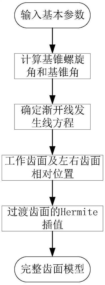
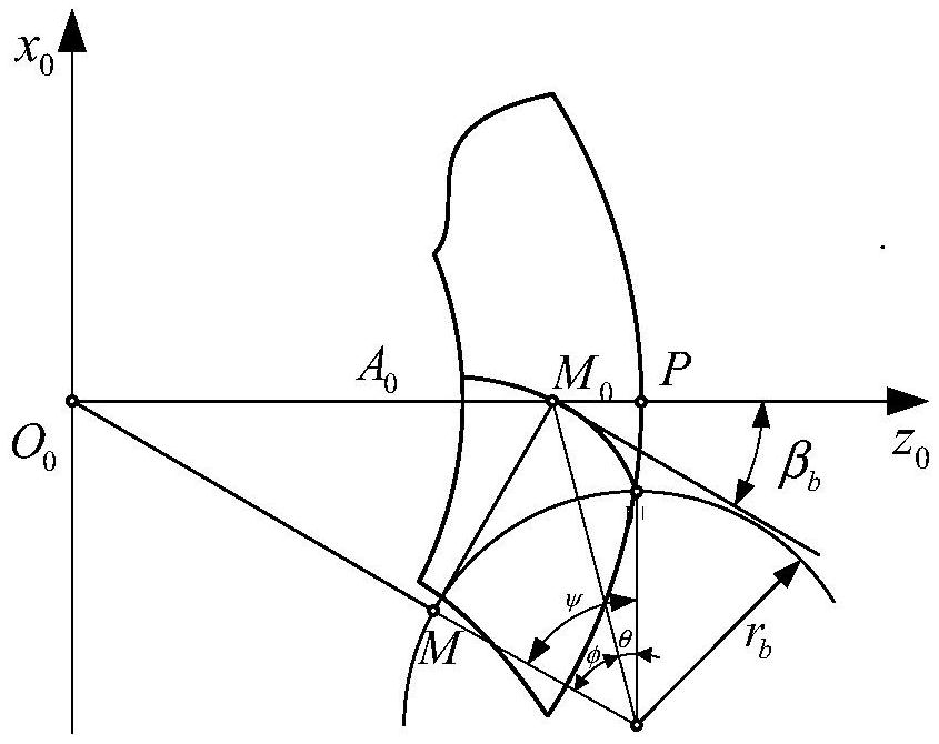
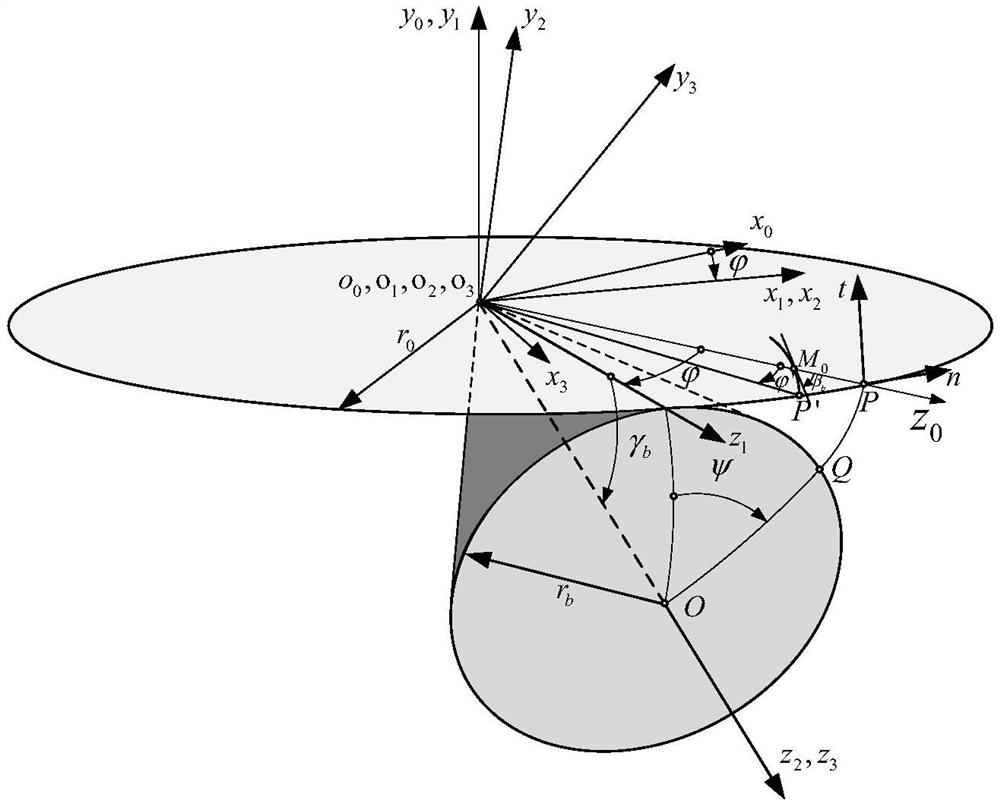
The invention discloses a method for designing the tooth surface of an involute spiral bevel gear. Both the tooth line and the tooth profile are involute. Based on the pitch cone parameters of the spiral bevel gear pair, the base cone helix angle is calculated; on the occurrence surface, the involute equation is determined according to the involute characteristics and the geometric relationship of the base cone midpoint helix angle, and it is used as the occurrence line ; With the help of coordinate transformation and phase difference relationship, the working tooth surface equation formed by the involute line is derived, and the relative position of the left and right tooth surfaces is further determined; the transitional tooth surface uses Hermite interpolation to obtain a continuous smooth transitional tooth surface to complete the complete tooth surface design. This method improves the load-carrying capacity of the tooth surface and reduces the sensitivity of the meshing performance to installation errors. The transitional surface adopts the Hermite interpolation method. Through weight coefficient control, different tooth root shapes can be obtained and the bending strength of the gear teeth can be improved.
Description
technical field [0001] The invention belongs to the technical field of gear transmission, in particular to a design method for the tooth surface of an involute spiral bevel gear. Background technique [0002] Spiral bevel gears are used to transmit power and movement in space intersecting axes or interlaced axes, and are widely used in aviation, automobiles and machine tools. With the development of technology, the requirements for its speed and load are getting higher and higher. High speed, heavy load and low weight are its development direction. The existing spiral bevel gears mainly include Gleason and Oerlikon teeth, and the corresponding tooth lines are arc and extended epicycloid respectively. This is due to the limitations of machine tools and cutting tools. It is only possible to choose between these two tooth profiles, thus limiting the tooth surface design and machining of high-performance spiral bevel gears. With the development of modern CNC machining centers ...
Claims
Login to View More Application Information
Patent Timeline
 Patent Type & AuthorityPatents(China)
IPC IPC(8): B23F9/00
CPCB23F9/00
Inventor苏进展阎志强封硕吴文
OwnerCHANGAN UNIV