Dissimilar metal pipe overlap joint and welding method thereof

A technology for lap joints and dissimilar metals, applied in the field of lap joints of dissimilar metal pipes and their welding, can solve the problems of inability to form a collision angle, limit the bearing capacity of the joint, and small area, so as to expand the area of ​​the metallurgical connection area and improve the collision Speed, the effect of improving the probability of matching

Inactive Publication Date: 2020-02-18
FUZHOU UNIV
View PDF6 Cites 5 Cited by
  • Summary
  • Abstract
  • Description
  • Claims
  • Application Information

AI Technical Summary

Problems solved by technology

In the traditional magnetic pulse welding process of metal pipes, due to the use of a joint structure in which the ends of the inner and outer pipes are overlapped in parallel, the magnetic pressure on the outer pipe is evenly distributed along the coil axis, and the gap between the inner and outer pipes is also equal. The plastic deformation of the uniform shrinkage of the tube causes most of the connection area of ​​the outer tube to collide with the inner tube vertically and cannot form an effective collision angle, so it is difficult to form a jet. Most of the connection area is a mechanical connection area, only at the end of the magnetic collector working area The area forms a weld seam about 1~2mm wide
The area of ​​the welding area is too small, which greatly limits the bearing capacity of the joint

Method used


Image

  • Dissimilar metal pipe overlap joint and welding method thereof
  • Dissimilar metal pipe overlap joint and welding method thereof
  • Dissimilar metal pipe overlap joint and welding method thereof

Examples


Embodiment 1

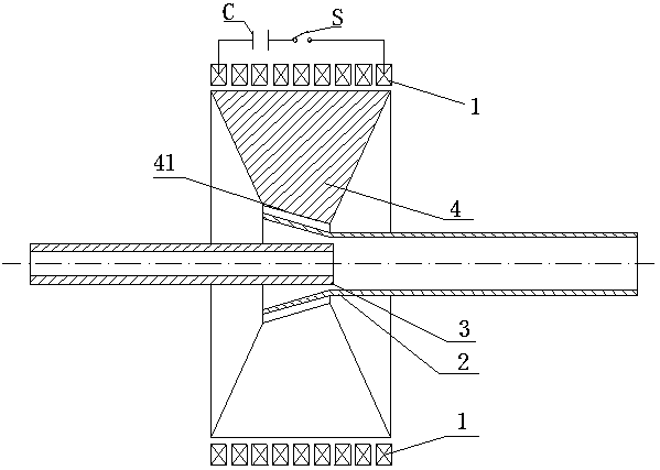
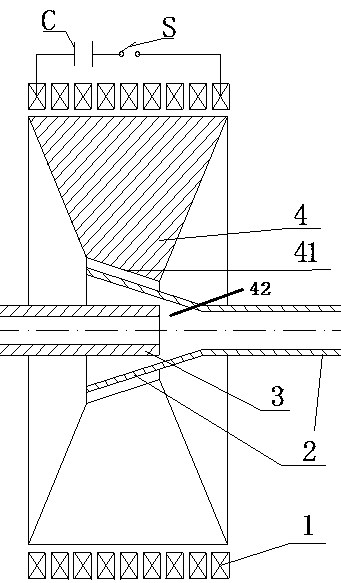
[0044] This embodiment includes a solenoid coil 1 , a magnet collector 4 , a high voltage switch S and a capacitor bank C.

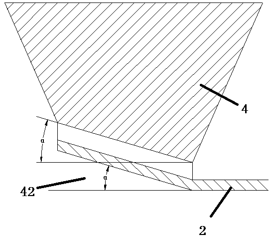
[0045] The material of the solenoid coil 1 is copper, and the material of the magnetic collector 4 is generally a copper alloy with low resistivity and high strength. , the working area 41 of the magnetic collector is designed as a conical surface structure, and the angle between the conical surface and the axial direction is defined as the cone angle α of the conical surface. 4°; any end of the outer tube 2 is flared, and the flare angle should be equal to the cone angle of the conical surface 41 in the working area of ​​the magnetic collector, and the final position relationship between the two should be parallel. The solenoid coil 1 is set on the outer surface of the magnetic collector 4, and the two are placed in a concentric circle. The capacitor bank C, the high voltage switch S, and the solenoid coil 1 are connected in series in the circuit.

[...

Embodiment 2

[0050] In this example, it is the connection of two equal-diameter pipes. The selected outer pipe 2 is a 3A21 aluminum alloy outer pipe with an outer diameter of 20mm, an inner diameter of 18mm, a wall thickness of 1mm, and a length of 100mm. The flare angle of the outer pipe 2 is 3˚~5˚, the flare angle selected in this example is 5˚. The inner pipe 3 is a No. 20 steel pipe, with an outer diameter of 20 mm, an inner diameter of 14 mm, a wall thickness of 3 mm, and a length of 80 mm. Other specific implementation methods are the same as the first embodiment.


PUM

PropertyMeasurementUnit
diameteraaaaaaaaaa
thicknessaaaaaaaaaa

Abstract

The invention puts forward a dissimilar metal pipe overlap joint. The dissimilar metal pipe overlap joint is applied to alignment of two pipes during magnetic pulse welding of the metal pipes and positioning of pipe fittings at welding equipment. The overlap joint comprises an outer pipe and an inner pipe; the welding end of the outer pipe and the welding end of the inner pipe are arranged in theworking zone of a field shaper of the welding equipment; the working zone of the field shaper adopts the conical surface structure; the welding end of the outer pipe is a trumpet-shaped flaring opening with the outer wall parallel with the conical surface of the working zone; the welding end of the inner pipe is inserted in the flaring opening and is adjacent to the small end of the flaring opening; and the pipe diameter of the welding end of the inner pipe is larger than or equal to the hole diameter of the small end of the flaring opening. When magnetic pulse welding is performed, the flaring opening generates the induction eddy due to the magnetic field of the field shaper; the magnetic field of the induction eddy repels the magnetic field, in the working zone, of the field shaper, so that the flaring opening collides with the welding end of the inner pipe at the high speed under the action of the repulsion force, and magnetic pulse welding is completed. According to the dissimilarmetal pipe overlap joint, the collision angle is favorably formed during magnetic pulse welding operation, the collision speed is increased, and the area of a metallurgical connection zone of the overlap joint is enlarged.

Description

technical field [0001] The invention relates to the field of welding technology, in particular to a lap joint of dissimilar metal pipes and a welding method thereof. Background technique [0002] With the development of the country's economy and technology, and the improvement of people's awareness of energy conservation and emission reduction, those mechanical components with high energy consumption and low efficiency in traditional manufacturing will be gradually eliminated. The lightweight structure can not only save metal and reduce the overall weight of mechanical parts, but also reduce energy consumption. For example, in the field of aerospace manufacturing, most of the seats and cabins of aircraft are made of aluminum alloy structures; in the field of automobile manufacturing, the body of Toyota Corolla series cars uses aluminum alloy frames; the main body and superstructure of ships use aluminum-steel composite Material. However, due to the large difference in phys...

Claims


Application Information

Patent Timeline
Patent Type & Authority Applications(China)
IPC IPC(8): B23K31/02B23K101/06
CPCB23K31/027B23K2101/06
Inventor 范治松卢鸿飞邓将华陈志腾黄顺强
Owner FUZHOU UNIV
Why Eureka
Try Eureka