Polishing pads and chemical mechanical polishing equipment

A polishing pad and polishing layer technology, which is applied in the direction of grinding/polishing equipment, metal processing equipment, grinding tools, etc., can solve the problems of wasting polishing liquid, reducing the utilization rate of polishing liquid, and destroying, so as to control the residence time and maintain excellent Performance, the effect of maintaining the polishing environment

Active Publication Date: 2021-08-24
XIAN ESWIN SILICON WAFER TECH CO LTD
View PDF6 Cites 1 Cited by
  • Summary
  • Abstract
  • Description
  • Claims
  • Application Information

AI Technical Summary

Problems solved by technology

[0004] At present, the shape of the polishing layer groove of the polishing pad is simple and the function is single. In the actual use process, there will be polishing waste liquid and waste debris that cannot be removed in time to block the groove and scratch the surface of the silicon wafer, or the polishing liquid stays in the groove for too long. Short lead to a decrease in the utilization rate of the polishing liquid, increase the consumption of the polishing liquid, etc., which will damage and hinder the transportation of the polishing liquid in the polishing area, the uniformity of distribution, the residence time, the mixing efficiency of the old and new polishing liquid, and the change of the silicon wafer, polishing pad and polishing liquid The temperature between the three affects the polishing rate and polishing effect of the silicon wafer surface, reduces the yield of the silicon wafer, wastes a large amount of polishing fluid, and shortens the service life of the CMP polishing pad, resulting in premature failure of the CMP polishing pad.

Method used


Image

  • Polishing pads and chemical mechanical polishing equipment
  • Polishing pads and chemical mechanical polishing equipment
  • Polishing pads and chemical mechanical polishing equipment

Examples


Embodiment 1

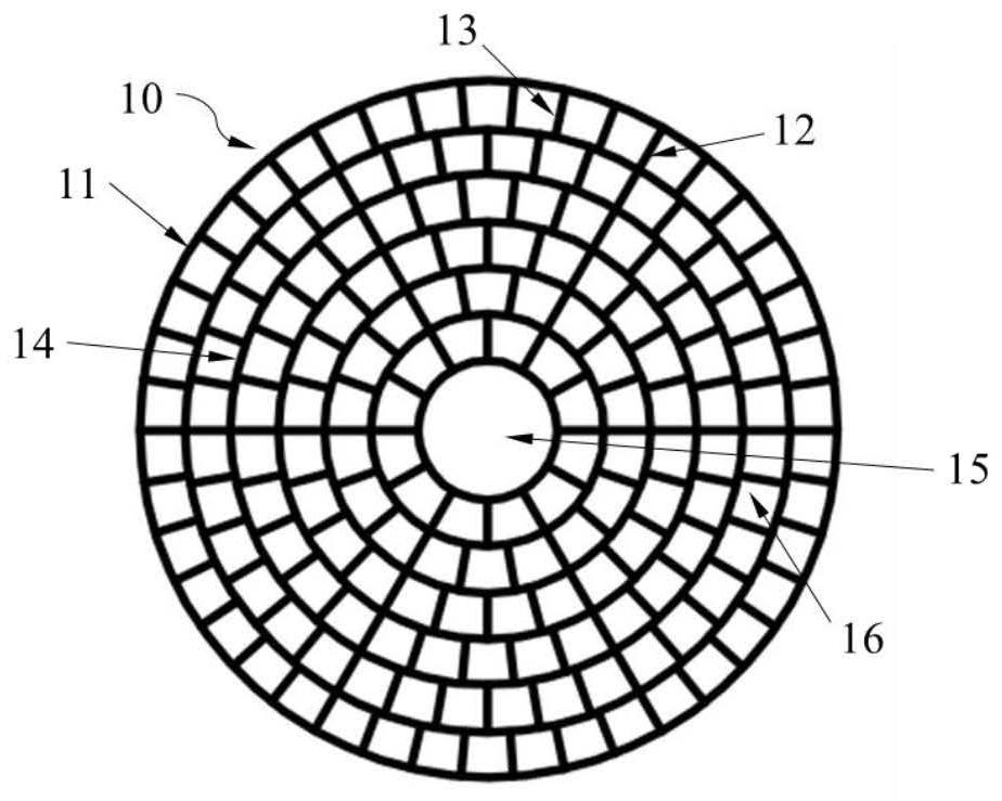
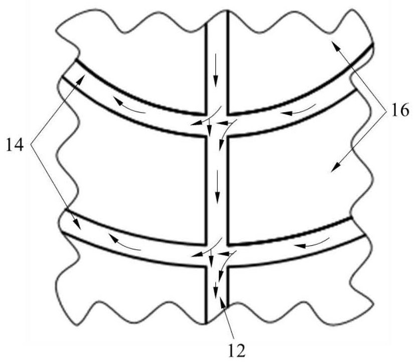
[0090] This example figure 1 with Figure 2a As shown, the polishing pad 10 includes a substrate layer and a polishing layer, and the polishing layer includes at least three circumferential grooves 14 arranged in sequence from the center 15 to the circumference 11 along the circumferential direction and a first radial groove 14 arranged along the radial direction. Groove 12 and second radial groove 13; Described first radial groove 12 connects circle center 15 and circumference 11, divides the area 16 between circle center 15 and circle 11 into circle sectors, the number of circle sectors Equal to the number of grooves of the first radial groove 12; said circle sector divides the polishing zone 16 between the adjacent circumferential grooves 14 evenly with an arithmetic progression from the center 15 to the circumference 11, forming a second diameter groove 13, the second radial groove 13 evenly divides the area between the k-1th circumferential groove and the kth circumferen...

Embodiment 2

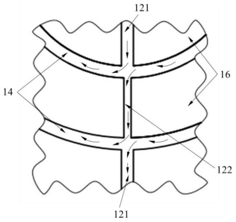
[0093] This embodiment is based on Embodiment 1, changing the width of the first radial groove 12, and dividing the first radial groove 12 into the first radial groove wide groove 121 and the first radial groove narrow groove 122, the first radial groove wide groove 121 and the first radial groove narrow groove 122 appear alternately along the radial direction as Figure 2b As shown, the width of the wide groove 121 of the first radial groove is equal to the width of the circumferential groove 14, and the width of the wide groove 121 of the first radial groove is greater than that of the narrow groove 122 of the first radial groove width. Dividing the first radial groove 12 into wide grooves and narrow grooves and alternately distributing them along the radial direction is beneficial to control the speed at which the polishing liquid flows out along the first radial groove 12, promotes uniform distribution of the polishing liquid as a whole, and maintains a stable polishing en...

Embodiment 3

[0095] This example image 3As shown, the polishing pad 210 includes a substrate layer and a polishing layer, and the polishing layer includes at least three circumferential grooves 214 arranged in sequence from the center 215 to the circumference 211 along the circumferential direction and a second radial groove 214 arranged along the radial direction. Groove 213, the second radial groove 213 from the center of circle 215 to the circumference 211 in an equiproportional sequence gradually increases and evenly divides the polishing zone 216 between adjacent circumferential grooves 214 and connects with the outer radial direction of the circumferential groove 214 The second radial groove 213 is evenly distributed on both sides of the inner second radial groove 213, the width of the circumferential groove 214 is equal to the width of the second radial groove 213 in the radial direction, and the second radial groove 213 The area between the k-1th circumferential groove and the kth...


PUM


Abstract

The invention provides a polishing pad and chemical mechanical polishing equipment, belonging to the technical field of semiconductors. The polishing pad includes a substrate layer and a polishing layer on the substrate layer, the polishing layer includes a plurality of concentric circumferential grooves arranged in the circumferential direction, and a plurality of grooves arranged in the radial direction and connected to adjacent circumferential directions Groove radial groove. The invention can improve the utilization rate of the polishing liquid, the service life of the polishing pad and the polishing quality.

Description

technical field [0001] The invention relates to the technical field of semiconductors, in particular to a polishing pad and chemical mechanical polishing equipment. Background technique [0002] In the process of multi-wire cutting, grinding and other processing, micro-defects will remain on the surface of the silicon wafer, a surface stress damage layer will be formed, and impurities such as various metal ions will be adsorbed. The clean and bright "mirror surface" with extremely low precision meets the technical requirements for silicon wafers for the preparation of various microelectronic devices. It is necessary to polish the surface of silicon wafers to remove micro-defects and surface damage layers caused by previous processes on the surface. [0003] Chemical mechanical planarization or chemical mechanical polishing (CMP) is one of the key technologies for planarizing or polishing the surface of silicon wafers, and it is also the only technology that can achieve globa...

Claims


Application Information

Patent Timeline
Patent Type & Authority Patents(China)
IPC IPC(8): B24B37/26B24B57/02
CPCB24B37/26B24B57/02
Inventor 蒲以松惠聪阴俊沛
Owner XIAN ESWIN SILICON WAFER TECH CO LTD
Why Eureka
Try Eureka