Traceable pN-scale force value calibration device and method

The technology of a calibration device and calibration method is applied in the direction of measurement devices, optical devices, and the measurement of force balance force, which can solve problems such as difficulty in setting up an experimental platform, difficulty in reproducing, and deviation of results.

Inactive Publication Date: 2020-02-18
TIANJIN UNIV
View PDF7 Cites 6 Cited by
  • Summary
  • Abstract
  • Description
  • Claims
  • Application Information

AI Technical Summary

Problems solved by technology

[0004] 1. By applying an active force to the sample, the sample is forced to move within a certain range, and then the active calibration method is used to analyze the motion state. This method is easy to establish a measurement model and is less affected by the exposure of the camera. There are certain requirements for size;
[0005] 2. By counting the thermal motion state of the trapped particles in the optical trap, the passive calibration method of analyzing the thermal motion of the trapped particles, this method has a relatively small error and can measure non-spherical objects, but the measurement results are easily affected by environmental factors;
[0006] 3. The direct measurement method by comparing the light momentum of all the scattered light around the captured particle with the light momentum of the incident light. This method has the highest accuracy, but it is difficult to build the experimental platform, and it is easy to lose part of the scattered light, which leads to deviations in the results.
[0007] To sum up, the current pN level optical trap binding force measurement schemes are all based on theoretical calculations. Due to the influence of factors such as the measurement resolution of the optical imaging system, it is difficult to guarantee the accuracy and traceability of the measurement, and it is difficult to reproduce

Method used


Image

  • Traceable pN-scale force value calibration device and method
  • Traceable pN-scale force value calibration device and method
  • Traceable pN-scale force value calibration device and method

Examples


Embodiment Construction

[0052] In order to further understand the invention content, characteristics and effects of the present invention, the following examples are given, and detailed descriptions are as follows in conjunction with the accompanying drawings:

[0053] 1. Estimate the magnitude of light pressure

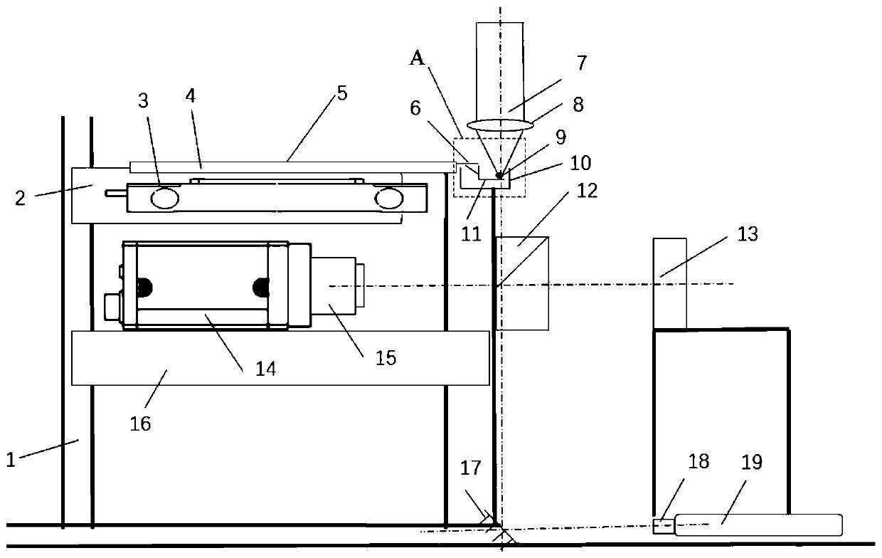
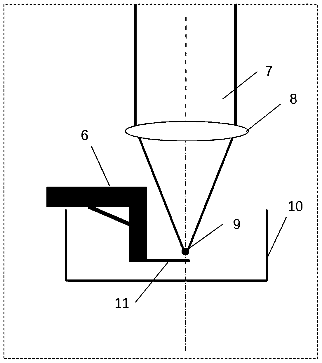
[0054] Normally, the optical tweezers system uses a 1064nm Nd:YAG laser, a linear polarization converter, and an objective lens with a large NA. The microsphere 9 part often uses micron-sized silicon balls or silicon dioxide balls, and the liquid environment is water.

[0055] The trapping force of optical tweezers on particles is generated from the change of momentum caused by the change of propagation direction when the beam with momentum is incident on the surface of the particle. According to Newton's second law, the binding force of optical traps can be obtained from the time change rate of momentum. According to Newton's second law law, the binding force of the optical trap can be exp...


PUM


Abstract

The invention discloses a traceable pN-scale force value calibration device and method, which is used for calibrating an optical trap binding force of an optical tweezer system. The optical tweezer system applies the optical trap binding force on a microsphere in a sample pool. The device comprises a force value sensing element, a displacement control system, and a free end displacement measurement system, wherein a free end of the force value sensing element is located in the sample pool and applies an action force on the microsphere in the sample pool; the force value sensing element is fixed on the displacement control system; the displacement control system achieves a nanoscale positioning precision for the force value sensing element, controls the force value sensing element to gradually approach the microsphere from a far end, and achieves mutual action between the force value sensing element and the microsphere; and the free end displacement measurement system measures relativedisplacements of the free end of the force value sensing element. The device and method disclosed by the invention has the advantages that the optical trap rigidity need not be obtained through approximate calibration; and errors caused by image distortions during measurement of relative displacements of the microsphere by optical imaging equipment can be avoided.

Description

technical field [0001] The invention relates to micro force value measurement, in particular to a traceable pN level force value calibration device and method. Background technique [0002] In the field of life sciences, the optical tweezers technology based on the pN-level optical trap effect has been widely used in the micro-manipulation of cells, organelles, chromosomes and other tiny organisms, and has been developed rapidly. It has unique advantages such as high efficiency and plays an increasingly important role in delicate processes such as biochemistry or biophysics. In the specific implementation process, the pressure deviation during the manipulation of optical tweezers will cause instability and uncontrollability in the capture process, and even lead to the loss of activity of living organisms, resulting in serious consequences such as cell necrosis. Therefore, the accuracy of the optical trap binding force is very demanding. strict. [0003] In terms of measure...

Claims


Application Information

Patent Timeline
Patent Type & Authority Applications(China)
IPC IPC(8): G01L25/00G01L1/08G01B11/02
CPCG01B11/02G01L1/08G01L25/00
Inventor 宋乐郑博轩袁宇焜顾春阳黄思雨朱欢
Owner TIANJIN UNIV
Why Eureka
Try Eureka