Comb tooth capacitive micro-electromechanical accelerometer structure

A technology of accelerometer and comb-tooth capacitance, which is applied in the field of micro-electromechanical accelerometer structure, can solve the problems of basic capacitance change, large anchor point, structural influence, etc., and achieve the goal of improving temperature stability, capacitance symmetry, and mechanical sensitivity Effect

Active Publication Date: 2020-02-18
XIAN FLIGHT SELF CONTROL INST OF AVIC
View PDF15 Cites 2 Cited by
  • Summary
  • Abstract
  • Description
  • Claims
  • Application Information

AI Technical Summary

Problems solved by technology

[0004] The comb teeth of the above-mentioned types of accelerometers usually use square long teeth. Considering that the force on the end of the comb is smaller than that on the root, the width of the end of the comb does not have to be the same as the root. The extra mass brought about by this will affect the indicators of the accelerometer. design
The comb groups of the above-mentioned types of accelerometers are usually distributed symmetrically up and down or left and right to form a differential capacitance, which is easily affected by the unevenness of the etching process during processing; in addition, when the temperature changes and the material expands and contracts, the gap between the comb teeth will change slightly. Changes, resulting in changes in the base capacitance, affecting the stability of the accelerometer scale coefficient
Finally, the anchor points of the above-mentioned types of accelerometers are usually large and far away, resulting in a structure that is easily affected by the anchoring material

Method used


Image

  • Comb tooth capacitive micro-electromechanical accelerometer structure
  • Comb tooth capacitive micro-electromechanical accelerometer structure
  • Comb tooth capacitive micro-electromechanical accelerometer structure

Examples


Embodiment Construction

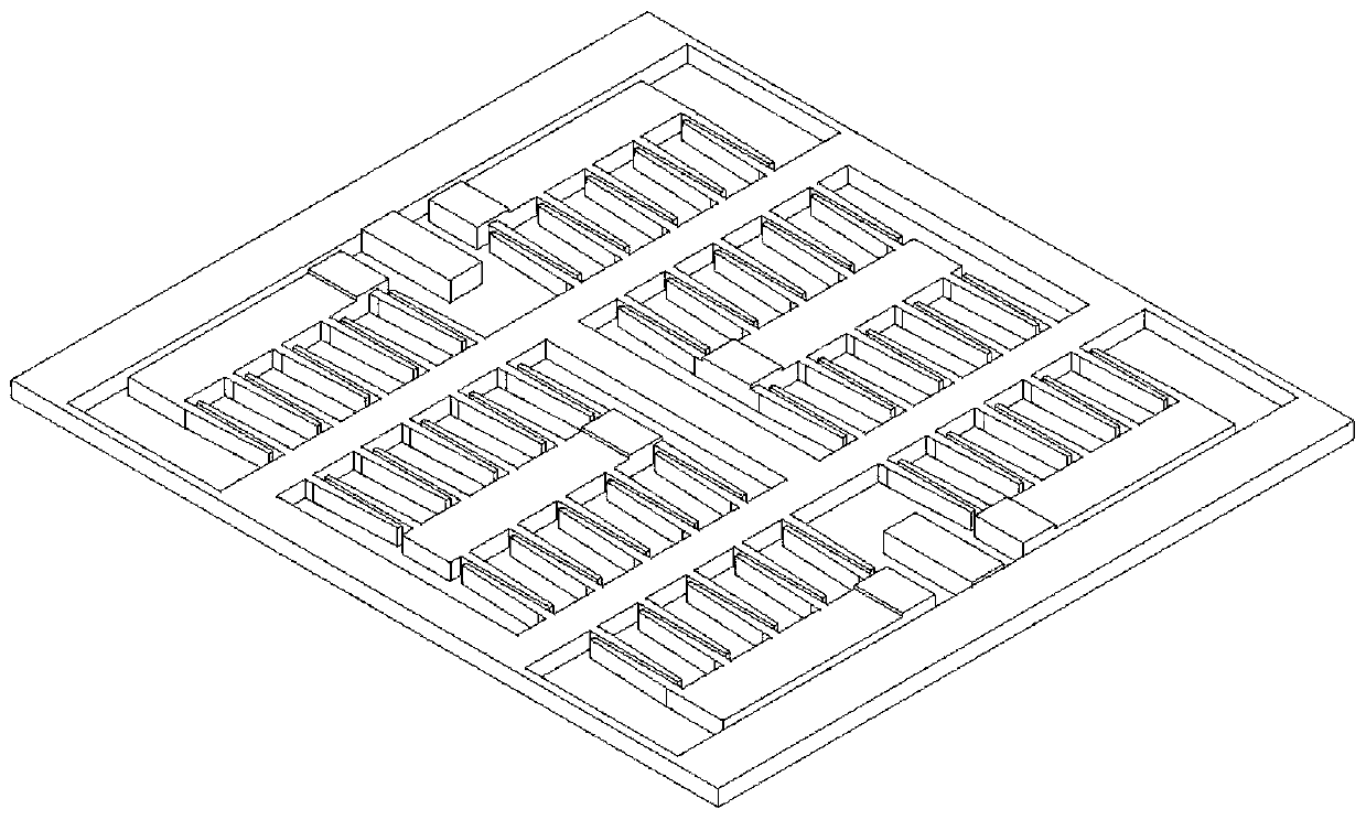
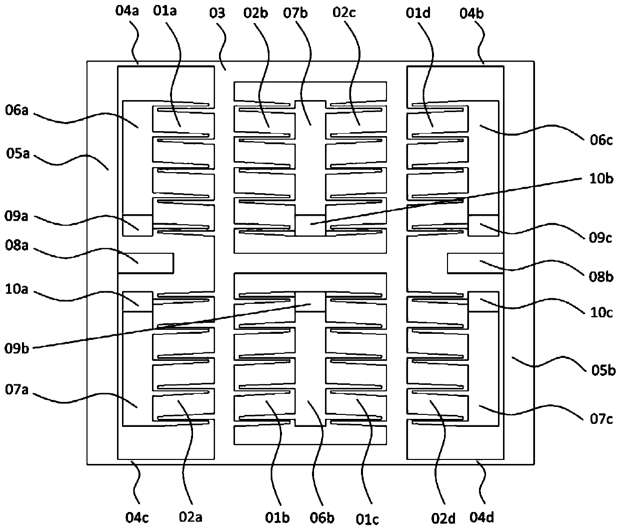
[0016] In order to understand the purpose, technical solutions and advantages of the present invention more clearly, the present invention will be further described in detail below in conjunction with the accompanying drawings and embodiments. For ease of description, the components in the following description are identified by numbers, and the sub-components of the components are identified by the numbers + lowercase letters of the components. For clarity, the substrate is not shown in the figure.

[0017] The invention provides a comb-tooth capacitive micro-electromechanical accelerometer structure, and the material of the structure is generally silicon or silicon carbide. figure 1 It is a three-dimensional schematic diagram of the structure of the comb-tooth capacitive micro-electromechanical accelerometer of the present invention, figure 2 Its top view diagram. Comb-tooth capacitive MEMS accelerometer structure of the present invention includes comb-tooth groups 01a-d,...


PUM


Abstract

The invention discloses a comb tooth capacitive micro-electromechanical accelerometer structure. The structure comprises comb tooth groups, a mass block, flexible beams, flexible beam support rods andcomb tooth support rods, wherein the mass block is a frame structure shaped like a Chinese character Ri; the comb tooth groups are variable-gap comb tooth groups; each comb tooth for forming the combtooth groups is a pentagonal comb tooth with a gradually varied comb tooth width at the overlapped area; the comb tooth groups are crossly distributed in the inner and outer sides of the mass block frame to form a differential capacitor; the movable comb teeth of the comb tooth groups are connected with the mass block and are suspended at two ends of the flexible beam support rods on the two outermost sides of the structure through four flexible beams at four corners of the mass block frame; and the fixed comb teeth of the comb tooth groups are connected with the comb tooth support rods. Thepentagonal comb teeth is capable of increasing the tooth pair number while keeping the tooth clearance ratio, so that benefit is brought to improve the sensitivity of the accelerometer. The crossly distributed comb tooth groups are capable of making up the capacitive differences caused by nonuniform etching process so as to improve the capacitive symmetry, and is also capable of compensating the influences, on the differential capacitor, caused by environment temperature change so as to improve the stability of a calibration factor of the accelerometer.

Description

technical field [0001] The invention belongs to the technical field of microelectromechanical accelerometer structures, and relates to a comb-tooth capacitive microelectromechanical accelerometer structure. Background technique [0002] The comb capacitive micro-electromechanical accelerometer has the advantages of small size, low power consumption, good stability, and strong overload capability. It is often used for acceleration, vibration, and inclination testing, and is widely used in medical, industrial, and military fields. [0003] The structure of a conventional comb capacitive MEMS accelerometer usually consists of a mass block, 4 sets of variable-gap comb teeth, 4 flexible beams and corresponding anchor points. Four sets of comb teeth are symmetrically distributed up and down on both sides of the mass block to form a differential capacitor. The fixed teeth of the comb set are connected to the anchor point, and the movable teeth are connected to the mass block. Four ...

Claims


Application Information

Patent Timeline
Patent Type & Authority Applications(China)
IPC IPC(8): G01P15/125G01P1/00
CPCG01P15/125G01P1/00
Inventor 牛昊彬孙国良王帅民李博洋
Owner XIAN FLIGHT SELF CONTROL INST OF AVIC
Why Eureka
Try Eureka