
Power electronic wire and terminal fixed connection equipment and operation method

A technology for terminal fixing and connecting equipment, applied in the direction of tightening/insulating connectors, connections, parts of connecting devices, etc. Ends fall off and other problems, to achieve the same degree of compression, avoid defective products, and avoid falling off

Active Publication Date: 2020-02-18
WENZHOU YIWO MASCH TECH CO LTD
View PDF9 Cites 2 Cited by
  • Summary
  • Abstract
  • Description
  • Claims
  • Application Information

AI Technical Summary

Problems solved by technology

[0005] The present invention provides a fixed connection device and operation method between a power electronic wire and a terminal, aiming to solve the following problems existing in the connection between the wire lug and the wire by using the crimping equipment for the wire and the wire lug in the prior art: (1) After the end of the wire is stuffed into the wire barrel of the wire lug, there is often a large margin in the radial direction of the wire barrel, and the end of the wire cannot be fixed well by simply pressing the wire barrel, resulting in the end of the wire being used later. (2) When using a wire lug to connect two wires, after fixing the end of one wire in the wire barrel, it is still necessary to manually pass the end of the other wire through the ring gasket. center hole, and then tighten the wire, the perforation process requires high operator experience, and the processing efficiency is low

Method used


Image

  • Power electronic wire and terminal fixed connection equipment and operation method
  • Power electronic wire and terminal fixed connection equipment and operation method
  • Power electronic wire and terminal fixed connection equipment and operation method

Examples


Embodiment Construction

[0033] The embodiments of the present invention will be described in detail below with reference to the accompanying drawings, but the present invention can be implemented in many different ways defined and covered by the claims.

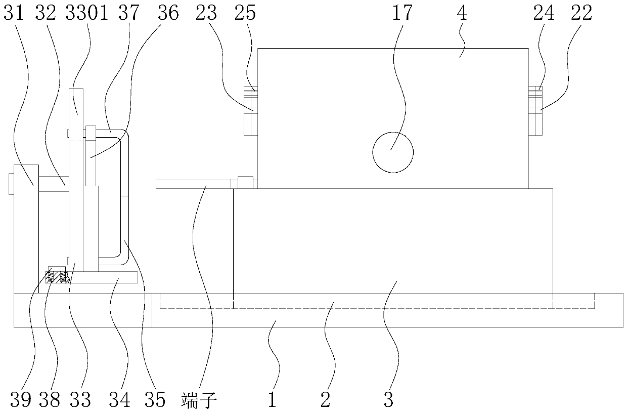
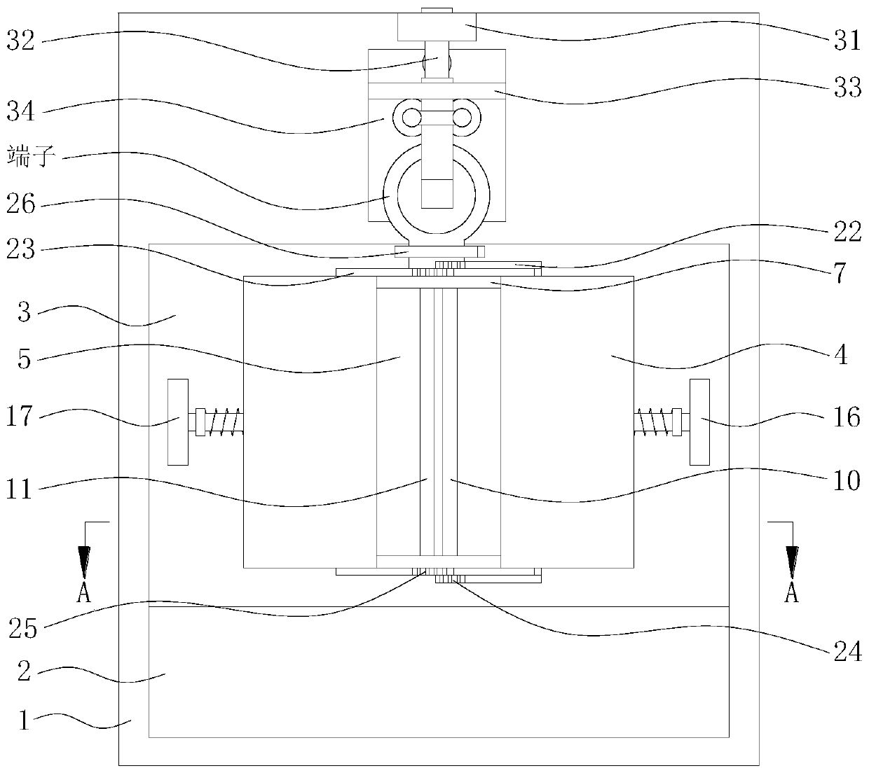
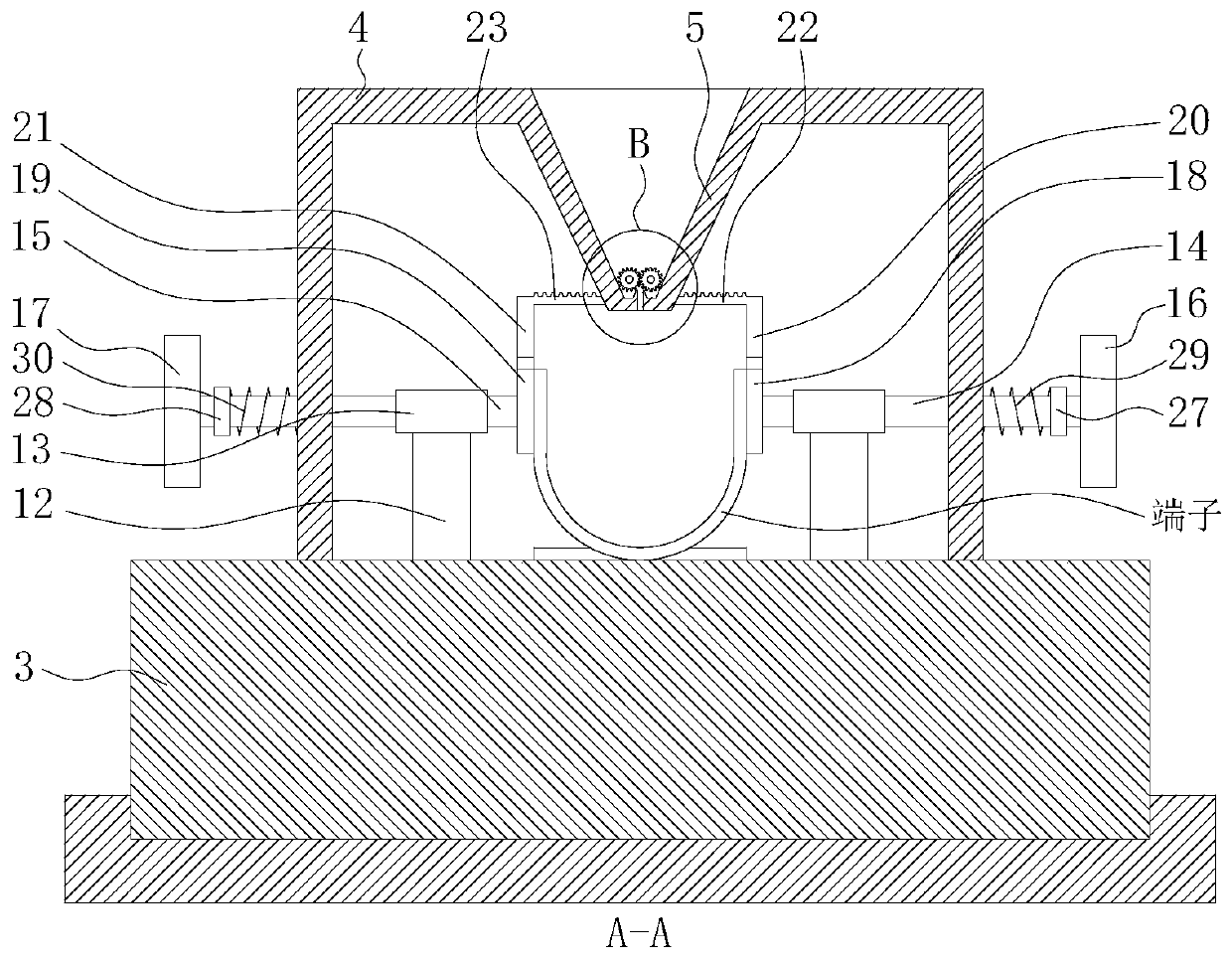
[0034] Such as Figure 1 to Figure 4 As shown, this embodiment provides a device for fixed connection between power electronic wires and terminals, where the terminal refers to a wire lug or other terminals similar to a wire lug, and the fixed connection refers to the fixed connection of two wires. The device includes a bottom plate 1, the upper surface of the bottom plate 1 is provided with a first chute 2, and a slider 3 is slidably fitted in the first chute 2. The upper surface of the slide block 3 is an iron horizontal plane and two symmetrical mounting frames 4 are vertically fixedly installed, and the longitudinal section of the mounting frame 4 is an inverted L-shape. Two baffle plates 5 are obliquely and fixedly installed on the top edge of...


PUM


Abstract

The invention belongs to the technical field of power equipment, and particularly relates to power electronic wire and terminal fixed connection equipment and an operation method. The equipment comprises a bottom plate; a sliding block is in sliding fit with the bottom plate; a mounting frame is arranged on the upper surface of the sliding block; two baffles are arranged on the mounting frame; a strip-shaped gap is reserved between the baffles; sealing plates are installed on the baffle end faces; a first gear rod and a second gear rod are rotationally mounted between the sealing plates; a limiting sleeve is installed on the sliding block; a first sliding rod and a second sliding rod are in sliding fit in the limiting sleeve; one end of the first sliding rod and one end of the second sliding rod are fixedly provided with a first pushing plate and a second pushing plate, the other ends are provided with a first pressing plate and a second pressing plate, and a first rack and a second rack are connected to the tops; and gears meshed with a first rack and a second rack are installed at the two ends of a first rotating shaft and a second rotating shaft. When the connecting device is used for connecting a wire nose and the two wires, the ends of the wires can be prevented from falling off from the wire nose; rapid wire tightening can be achieved, the perforating accuracy is improved, and the machining efficiency is improved.

Description

technical field [0001] The invention belongs to the technical field of wire harness terminal connection, and in particular relates to a fixed connection device and an operation method for a power electronic wire and a terminal. Background technique [0002] In electrical equipment, terminals refer to wiring terminals, also called wiring terminals. The types of terminals are divided into single hole, double hole, socket and hook, etc. Classified from the material, the terminals are divided into silver-plated copper, galvanized copper, copper, aluminum, iron and so on. Terminals are often used for connection and continuation of wire ends, which can make the connection between wires and electrical appliances and between wires and wires stronger. The wire lug is a common terminal, which consists of a wire barrel and a ring gasket, and is mainly used for 4mm 2 The above stranded wires are connected. The traditional method of connecting wires and wire lugs is that the operator...

Claims


Application Information

Patent Timeline
IPC IPC(8): H01R43/048H01R11/20H01R13/639H01R13/629
CPCH01R43/048H01R11/20H01R13/639H01R13/629
Inventor 李福香朱幼新
Owner WENZHOU YIWO MASCH TECH CO LTD
Learn More