
Induction coil copper pipe forming device

A molding device and induction coil technology, applied in the direction of molding tools, metal processing equipment, manufacturing tools, etc., to achieve the effect of beautiful eddy current loss, low labor intensity of workers, and small eddy current loss

Inactive Publication Date: 2020-02-21
HUAIBEI PINGXIANG ELECTRIC FURNACE
View PDF5 Cites 0 Cited by
  • Summary
  • Abstract
  • Description
  • Claims
  • Application Information

AI Technical Summary

Problems solved by technology

The existing winding induction coils are all solenoids. To arrange the copper tubes horizontally, the copper tubes are required to be bent at the appropriate position, and the copper tubes are bent to the same size and radian without special tools. is impossible, therefore, a device needs to be developed

Method used


Image

  • Induction coil copper pipe forming device

Examples


Embodiment 1

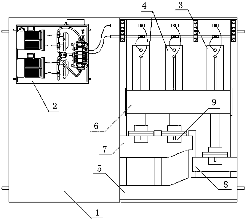
[0016] Such as figure 1 A kind of induction coil copper pipe forming device shown, comprises frame 1, fixed mold 5 that is installed on frame 1, is provided with hydraulic top fixed frame 6 on frame 1, is installed on hydraulic top fixed frame 6 Mold hydraulic jack 4, copper pipe fixed hydraulic jack 3, movable mold hydraulic jack 4 connected to movable mold 7, copper tube fixed hydraulic jack 3 connected to fixed block 8, bending arcs are set on fixed mold 5 and movable mold 7, and movable mold hydraulic pressure The top 4 and the copper pipe fixed hydraulic top 3 are connected to the hydraulic pump station 2 .

[0017] When working, first replace the mold according to the size of the copper tube, install the fixed mold and the movable mold, then use the copper tube to fix the hydraulic jack 3, press the copper tube, and then drive the hydraulic jack 4 of the movable mold to press.

Embodiment 2

[0019] As a specific structural design of Embodiment 1, two hydraulic jacks 4 of the movable mold are arranged in parallel. In order to ensure the bending effect, we designed two movable mold hydraulic jacks 4, this design, after the copper tube is fixed by the hydraulic jack 3, it is easier to bend into the desired shape.

[0020] The movable mold 7 is connected with the hydraulic rods of the two movable mold hydraulic jacks 4 through the mold mounting seat 9 .

[0021] The copper tube fixed hydraulic jack 3 is connected to the fixed block 8 through the mounting seat.

[0022] A chute is set on the frame 1 under the movable mold 7 and the fixed block 8, and a slide block is set on the movable mold 7 and the fixed block 8 on the chute. This structural design allows the movement of the movable mold 7 and the fixed block 8 to be more precise and run more smoothly.

[0023] The bending radian is set on the movable mold 7 at the adjacent part of the movable mold 7 and the fixed ...


PUM


Abstract

The invention discloses an induction coil copper pipe forming device. The induction coil copper pipe forming device comprises a machine frame and a fixed mold installed on the machine frame; the machine frame is provided with a hydraulic jack fixing frame, and movable mold hydraulic jacks and a copper pipe fixing hydraulic jack are installed on the hydraulic jack fixing frame; the movable mold hydraulic jacks are connected with a movable mold, and the copper pipe fixing hydraulic jack is connected with a fixing block; the fixed mold and the movable mold are provided with bending radians; and the movable mold hydraulic jacks and the copper pipe hydraulic jack are connected with a hydraulic pump station. The induction coil copper pipe forming device is easy to operate and control, low in labor intensity of workers, high in working efficiency and consistent in forming, and a manufactured induction coil is small in magnet yoke eddy current loss and beautiful.

Description

technical field [0001] The invention relates to an induction coil copper tube forming device, which belongs to the technical field of induction processing equipment. Background technique [0002] At present, the energy-saving measures for high-power coreless induction furnaces include increasing the induction coil voltage, reducing the induction coil current, selecting the appropriate operating frequency, and reducing losses by copper tube wall thickness, cross-sectional area, magnetic field screen, and using oriented silicon steel sheets. The shape of the induction coil can be changed to reduce the induction of the yoke to achieve energy saving effect. According to the principle of magnetic field cutting, the induced current generated by the conductor perpendicular to the alternating magnetic field is the largest, and the induced current generated by the conductor parallel to the alternating magnetic field is zero. For this reason, it is necessary to make the yoke parallel...

Claims


Application Information

Patent Timeline
Patent Type & Authority Applications(China)
IPC IPC(8): B21D7/08B21D37/10
CPCB21D7/085B21D37/10
Inventor 史万平
Owner HUAIBEI PINGXIANG ELECTRIC FURNACE
Learn More