
Composite forming method for thick spiral blade

A technology of helical blade and composite forming, applied in forming tools, gas flame welding equipment, manufacturing tools, etc., can solve the problems such as the inability to control the inner and outer diameters well, the narrow flow space of the cast metal, and the easy rebounding and irregularity of the forming. The effect of small pitch size error, fast pressing speed and stable molding quality

Active Publication Date: 2020-02-21
中铁工程装备集团盾构制造有限公司
View PDF4 Cites 2 Cited by
  • Summary
  • Abstract
  • Description
  • Claims
  • Application Information

AI Technical Summary

Problems solved by technology

[0002] At present, large thick spiral blades are generally cast and formed, and small thin spiral blades are generally formed by cold pressing. Because the spiral blade is a special space surface shape, casting is difficult and the cost of casting is relatively high. The flow space of cast metal is relatively narrow, and the melting of metal Poor fluidity leads to poor material properties; cold press forming is suitable for small spiral blades or spiral blades with low pressure, and the forming is easy to rebound and irregular
Large thick helical blades are formed by cold drawing or direct hot pressing or cold pressing. Cold drawing forming does not have strict requirements on curved surfaces, and the inner and outer diameters of direct pressing forming cannot be well controlled.

Method used


Image

  • Composite forming method for thick spiral blade
  • Composite forming method for thick spiral blade
  • Composite forming method for thick spiral blade

Examples


Embodiment Construction

[0024] A composite molding method of a thick helical blade of the present invention will be described in more detail below in conjunction with the accompanying drawings and through specific implementation methods.

[0025] In describing the present invention, it should be understood that the terms "upper", "lower", "front", "rear", "left", "right", "top", "bottom", "inner", " The orientation or positional relationship indicated by "outside", etc. is based on the orientation or positional relationship shown in the drawings, and is only for the convenience of describing the present invention and simplifying the description, rather than indicating or implying that the referred device or element must have a specific orientation, so as to Specific orientation configurations and operations, therefore, are not to be construed as limitations on the invention.

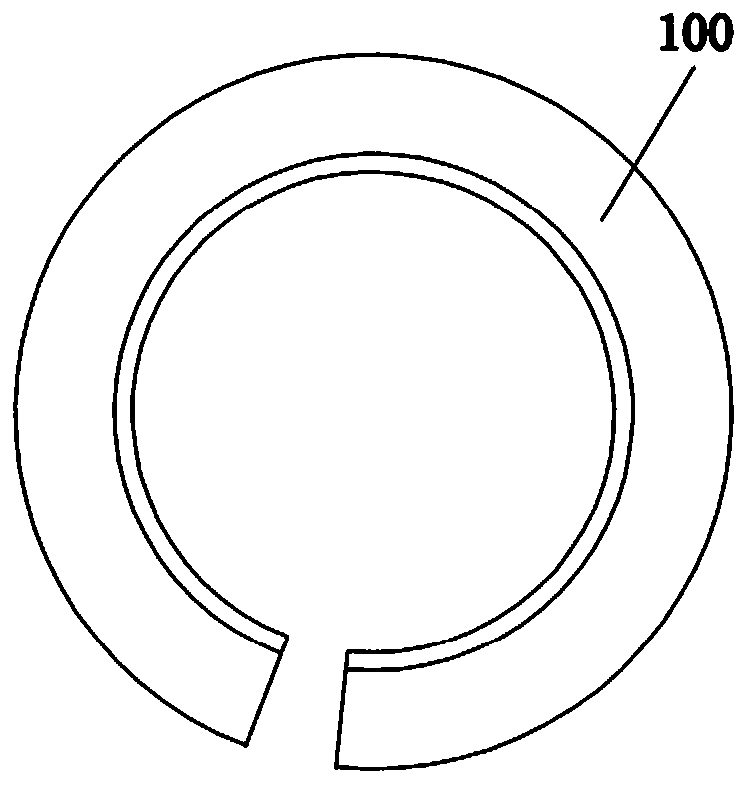
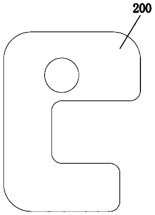
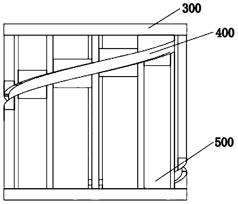
[0026] see Figure 1-Figure 4 , the present embodiment discloses a thick helical blade composite molding method, comprising ...


PUM


Abstract

The invention relates to the technical field of spiral blade forming machining, and particularly relates to a composite forming method for a thick spiral blade. The method comprises the following steps that a, blanking is carried out, and a plane body spiral blade blank blanking graph is calculated according to a spiral blade expansion calculation formula; b, a plane body spiral blade blank is heated, and the plane body spiral blade blank is converted into austenite at the high temperature; c, the plane body spiral blade blank is drawn, the first end of the edge of an inner hole notch of the high-temperature plane body spiral blade blank is fixed, the second end of the edge of the inner hole notch of the high-temperature plane body spiral blade blank is drawn through hoisting equipment, the inner spiral line of the spiral blade is stretched to the required size, and the plane body spiral blade blank is initially formed into a spiral blade; and d, the initially-formed spiral blade is placed on a prefabricated spiral mold, and pressure is applied to the prefabricated spiral mold through a press machine to press the prefabricated spiral mold into a standard thick spiral blade. According to the method, the inner diameter and the outer diameter of the formed spiral blade can be guaranteed, the method is suitable for mass production of thick spiral blades, the efficiency is high, andthe forming quality of the spiral blade is stable.

Description

technical field [0001] The invention relates to the technical field of forming and processing of spiral blades, in particular to a compound forming method for thick spiral blades applied to spiral blades of screw conveyors, shaft drilling machines and the like. Background technique [0002] At present, large thick spiral blades are generally cast and formed, and small thin spiral blades are generally formed by cold pressing. Because the spiral blade is a special space surface shape, casting is difficult and the cost of casting is relatively high. The flow space of cast metal is relatively narrow, and the melting of metal Poor fluidity leads to poor material performance; cold press forming is suitable for small spiral blades or spiral blades with low pressure, and the forming is easy to rebound and irregular. Large thick helical blades are formed by cold drawing or direct hot pressing or cold pressing. Cold drawing forming does not have strict requirements on curved surfaces,...

Claims


Application Information

Patent Timeline
Patent Type & Authority Applications(China)
IPC IPC(8): B21D22/20B21D37/10B21D37/16B23K7/00
CPCB21D22/20B21D22/208B21D37/10B21D37/16B23K7/00
Inventor 张峰林张哲学李宁师清豪张亚沛
Owner 中铁工程装备集团盾构制造有限公司
Learn More