A kind of deburring equipment for hollow bridge processing

A hollow bridge and burr technology, which is applied in the field of deburring equipment for hollow bridge processing, can solve the problems of low efficiency and manpower consumption, and achieve the effects of quality assurance, high work efficiency, and stable deburring

Active Publication Date: 2020-09-11
ANHUI AUTOMATION INSTR
View PDF1 Cites 0 Cited by
  • Summary
  • Abstract
  • Description
  • Claims
  • Application Information

AI Technical Summary

Problems solved by technology

[0005] The purpose of the present invention is to solve the problem of labor-intensive and low efficiency in the prior art, and propose a deburring equipment for hollow bridge processing

Method used


Image

  • A kind of deburring equipment for hollow bridge processing
  • A kind of deburring equipment for hollow bridge processing
  • A kind of deburring equipment for hollow bridge processing

Examples


Embodiment 1

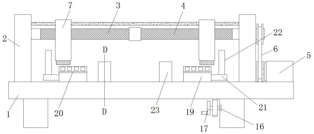
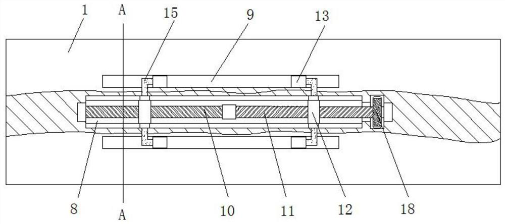
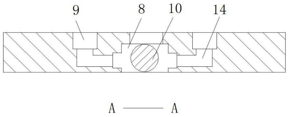
[0032] refer to Figure 1-7, a kind of deburring equipment for hollow bridge processing, comprising a machine 1, a support plate is fixed on both sides of the lower end of the machine 1, a support seat 2 is fixedly connected to both sides of the upper end of the machine 1, and two support seats 2 The side close to the upper end is respectively connected to the first screw 3 and the second screw 4 through rolling bearings, and the screw threads of the first screw 3 and the second screw 4, as well as the third screw 10 and the fourth screw 11, have opposite screw threads, and the machine 1 A servomotor 5 is also fixed on one side of the upper end surface, and the output end of the servomotor 5 is connected with the screw rod 2 4 through the transmission device 6. The outer wall of the screw rod 1 3 and the screw rod 2 4 is fixedly connected with a deburring device 7 for deburring. The burr device 7 comprises a mounting seat 701, and the mounting seat 701 is threadedly connected ...

Embodiment 2

[0035] Such as figure 1 and 7 As shown, this embodiment is basically the same as Embodiment 1. Preferably, the bridge fixing device 23 includes a support seat 2301, and the support seat 2301 is fixed on the sliding block 13, and the upper part of the support seat 2301 is screwed. Rotating rod 2302, the two ends of rotating rod 2302 are fixedly connected with extruding plate 1 2303 and rotating handle 2304 respectively, and extruding plate 1 2303 is close to the side of the center of machine table 1, and the end of extruding plate 1 2303 is close to the center of machine table 1. A cylindrical barrel 2305 is fixedly connected, and the inner wall of the cylindrical barrel 2305 is slidably connected with a pressure rod 2306. A spring 2307 is fixed between the pressure rod 2306 and the bottom surface of the cylindrical barrel 2305. One end of the pressure rod 2306 is fixedly connected with an extrusion plate 2308. A rubber head 2309 is fixed on the side of the second plate 2308 a...

Embodiment 3

[0038] Such as Figure 7 As shown, this embodiment is basically the same as Embodiment 1. Preferably, there are multiple cylindrical barrels 2305 that are evenly distributed on the end surface of the extruded plate 1 2303 .

[0039] In this embodiment, a plurality of cylindrical barrels 2305 are provided to ensure that the rubber head 2309 is pressed evenly on the bridge frame, thereby ensuring the stability of the bridge frame during deburring.


PUM


Abstract

The invention discloses a burr removing device for hollow bridge machining. The burr removing device comprises a machine table; supporting plates are fixed to the two sides of the lower end surface ofthe machine table correspondingly; first supporting seats are fixedly connected to the two sides of the upper end of the machine table correspondingly; a first screw rod and a second screw rod are rotationally connected to the sides, close to each other, of the upper ends of the two first supporting seats through rolling bearings correspondingly; a servo motor is further fixed to one side of theupper end surface of the machine table; the output end of the servo motor is rotationally connected with the second screw rod through a conveying apparatus; burr removing apparatuses are fixedly connected to the outer walls of rod bodies of the first screw rod and the second screw rod correspondingly; each burr removing apparatus comprises a mounting seat; the mounting seats are connected to the outer walls of the rod bodies of the first screw rod and the second screw rod through screw threads; grooves are formed in the lower ends of the mounting seats; threaded holes are formed in the middlesof the inner top surfaces of the grooves; and threaded rods are fixedly connected to the inner walls of the threaded holes through screw threads. By means of the burr removing device for hollow bridge machining, burr removing work of hollow bridges which are different in specification and length can be achieved, the equipment application range is wide, and the working efficiency is high.

Description

technical field [0001] The invention relates to the technical field of hollow bridge processing auxiliary equipment, in particular to a deburring equipment for hollow bridge processing. Background technique [0002] In the process of cable installation and laying, it is necessary to use the power bridge, which can protect the circuit inside the power bridge, avoid the circuit from being exposed to the outside, ensure the safety of use, and also prevent the line from being suspended due to gravity. Inconvenient, there will be burrs on the surface of the cable tray after production, and if it is not treated, the surface will be easily damaged after the cable is installed. [0003] After retrieval, the patent application publication number 201820298762.8 discloses a cable bridge grinding device, including bridge grinding table, table legs, grinding wheel, central support shaft, motor, bearing, bridge grinding slot, slot fixing frame, and grinding wheel drive Plate, bottom fixe...

Claims


Application Information

Patent Timeline
Patent Type & Authority Patents(China)
IPC IPC(8): B24B9/04B24B55/12B24B41/06
CPCB24B9/04B24B41/06B24B55/12
Inventor 柯正伟柯正涛
Owner ANHUI AUTOMATION INSTR
Why Eureka
Try Eureka