Multi-joint robot engraving machine

A multi-joint robot, engraving machine technology, applied in the direction of manipulator, program control manipulator, metal processing mechanical parts, etc., can solve the problems of engraving quality, damage to engraving knife, low efficiency of knife replacement, etc. scope, increased efficiency, reduced labor and labor costs

Pending Publication Date: 2020-02-21
HEFEI SIGNRIGHT NUMERICAL CONTROL EQUIP
View PDF0 Cites 5 Cited by
  • Summary
  • Abstract
  • Description
  • Claims
  • Application Information

AI Technical Summary

Problems solved by technology

[0003] There is a way of engraving in carving, which is cavity carving for carved products. Cavity carving is an important form of artistic expression in traditional carving techniques, but it is very difficult in actual operation and requires manual carving in a narrow space. , the existing equipment cannot carry out the cavity drop operation, and the existing programming operation is limited to plane engraving. In addition, the tool change operation of the engraving machine is troublesome. When changing the tool, the engraving end needs to be retracted to the knife release mechanism. Then take the knife from the cutter head, so the efficiency of tool replacement is low. During the cavity carving process, the carving knife enters and exits the inner cavity of the carved object, which is easy to cause damage, and the positioning needs to be repeated, which will affect the quality of the carving.

Method used


Image

  • Multi-joint robot engraving machine
  • Multi-joint robot engraving machine
  • Multi-joint robot engraving machine

Examples


Embodiment Construction

[0028] The following will clearly and completely describe the technical solutions in the embodiments of the present invention with reference to the accompanying drawings in the embodiments of the present invention. Obviously, the described embodiments are only some, not all, embodiments of the present invention. Based on the embodiments of the present invention, all other embodiments obtained by persons of ordinary skill in the art without making creative efforts belong to the protection scope of the present invention.

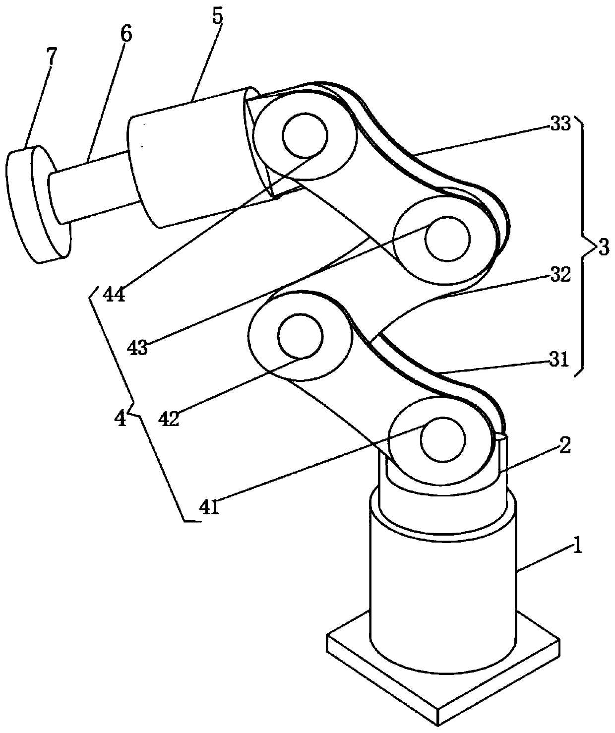
[0029] like Figure 1-4 As shown, the present invention provides a technical solution: a multi-joint robot engraving machine, including a rotating motor 1, the output end of the rotating motor 1 is fixedly connected with a mounting base 2, and the top of the mounting base 2 is fixedly connected with a multi-joint crank arm 3 , the multi-joint crank arm 3 is provided with a second angle motor 4 to adjust the state of the multi-joint crank arm 3, the top of the ...


PUM


Abstract

The invention relates to a multi-joint robot engraving machine. The multi-joint robot engraving machine comprises a rotary motor, wherein an installation seat is fixedly connected to an output end ofthe rotary motor; a multi-joint crank arm is fixedly connected to the top of the installation seat; and a second angle motor is arranged on the multi-joint crank arm to adjust the state of the multi-joint crank arm. According to the multi-joint robot engraving machine, in specific operation, a drive device moves downwards under the driving of an electric push rod, the drive device makes contact with a location clamping sleeve, and under the rotation of the drive device, the location clamping sleeve can be driven to rotate; a drill bit installation mechanism is connected into a rotary block ina sleeved manner, so that a drill bit can be driven to rotate; during changing for the drill bit, the drive device ascends, a tool changing disc rotates, and in this way, the step of tool changing canbe rapidly carried out, so that the drill bit can be changed without the need of enabling an engraving tool disc to enter into and exit out of a cavity body; and the tool changing manner is rapid, and capable of increasing the operation efficiency, and carrying out changing operation on a plurality of tools in a short time.

Description

technical field [0001] The invention relates to the technical field of multi-joint robot engraving machines, in particular to a multi-joint robot engraving machine for cavity carving. Background technique [0002] Engraving is a combination of drilling and milling in terms of processing principle. The various data input modes of the engraving machine can be set according to different drilling and milling modes. There are two types of computer engraving machines: laser engraving and mechanical engraving, both of which are divided into high-power and low-power. Because the application range of engraving machines is very wide, it is necessary to understand the most suitable application range of various engraving machines. Low-power ones are only suitable for two-color boards, architectural models, small signs, three-dimensional handicrafts, etc., while carving jade, metal, etc. requires a power of more than 1500W. A high-power engraving machine can do what a low-power engravi...

Claims


Application Information

Patent Timeline
Patent Type & Authority Applications(China)
IPC IPC(8): B25J11/00B25J9/12B23D79/00B23Q3/157
CPCB23D79/00B23Q3/15706B25J9/126B25J11/005
Inventor 袁昌荣
Owner HEFEI SIGNRIGHT NUMERICAL CONTROL EQUIP
Why Eureka
Try Eureka