A limit device and clamping method for heat treatment of a double-layer structure welded assembly

A double-layer structure and limiting device technology, applied in heat treatment furnaces, heat treatment equipment, furnaces, etc., can solve the problems of poor concentricity of the inner and outer layers, uneven gaps at the exit of the big head, and increased calibration workload, etc. The effect of good condition, shortened processing cycle and convenient and quick disassembly

Active Publication Date: 2021-05-28
CHINA HANGFA GUIZHOU LIYANG AVIATION POWER CO LTD
View PDF12 Cites 0 Cited by
  • Summary
  • Abstract
  • Description
  • Claims
  • Application Information

AI Technical Summary

Problems solved by technology

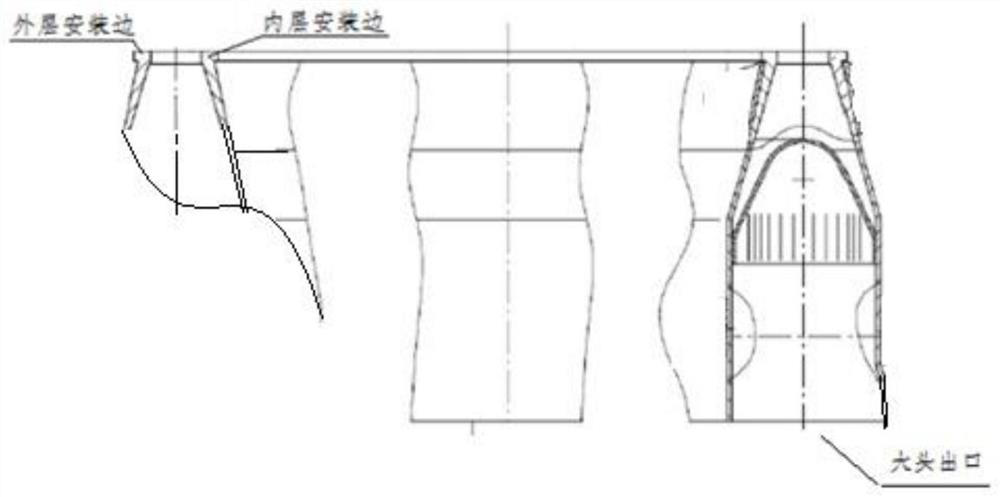
[0002] like figure 1 As shown, in the assembly process of aero-engine components, it involves the welding of a double-layer structure assembly. After welding and heat treatment, the deformation of the inner and outer rings is large, and the post-machining correction workload is very large. During the processing, it is reflected that the part affects the processing progress.
When turning the inner and outer mounting edges of the part, the deformation of the part will be large, the concentricity of the inner and outer mounting edges will be poor, the calibration workload will be large, and the turning process will cut into the main body of the part, etc.
Because there is no matching special tooling for the heat treatment of this part, the welding stress heat treatment is carried out in a free state, resulting in large deformation of the part after heat treatment, poor concentricity of the inner and outer layer mounting edges, and uneven gap at the exit of the big head, which increases the heavy calibration workload of subsequent turning processing

Method used


Image

  • A limit device and clamping method for heat treatment of a double-layer structure welded assembly
  • A limit device and clamping method for heat treatment of a double-layer structure welded assembly

Examples


Embodiment Construction

[0032] The present invention will be further described below in conjunction with accompanying drawing and specific embodiment, but should not be interpreted as that the scope of the subject matter of the present invention is only limited to following embodiment, under the situation of not departing from above-mentioned technical thought of the present invention, all according to this field Various modifications, substitutions and alterations made by ordinary technical knowledge and common means are included in the scope of the present invention.

[0033] In this embodiment, the limit device is designed and used according to the following steps:

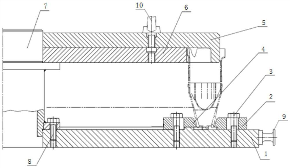
[0034] Design and manufacture a set of limit devices according to the size of the inner and outer mounting sides of the actual parts and the outlet of the big head. The assembly part is chamfered to facilitate assembly. The limit device and the assembly state are as follows figure 2 As shown, the limiting device for the heat treatmen...


PUM


Abstract

The present invention discloses a limited device and clamping method for the heat treatment of double -layer structure welding composition. The limit device includes the outer disk, inner plate, chassis, attentive shaft, and pressure plate.The disk, and the three are assembled on the heart axis.The outer surface of the outer disk is a first ring -shaped outer cylinder, and the inner surface of the inner surface of the outer structure of the first ring -shaped outer cylinder and the double -layer structure welding is tight;The outer surface of the inner structure of the inner structure of the second ring -shaped outer cylinder and the double -layer structure welding is tight; the upper end of the chassis is set with a pressure plate connected by the first bolt, and the outer installation edges of the outer layer of the double -layer structure welding component areThe inner layer is installed between the upper end of the pressure plate and the upper end of the chassis.The restriction device of the present invention is used for the installation of the installation of the inner and outer layers of the inner and outer layers of the inner and outer layers of the inner and outer layers.A pre -school volume to ensure assembly requirements.

Description

technical field [0001] The invention belongs to the technical field of thermal processing, and relates to a limiting device and a clamping method for heat treatment of a double-layer structure welding assembly. Background technique [0002] Such as figure 1 As shown, in the assembly process of aero-engine components, welding of a double-layer structure assembly is involved. After welding and heat treatment, the inner and outer rings are deformed greatly, and the workload of post-machining correction is very large. During the processing, it is reflected that the part affects the processing progress. When turning the inner and outer mounting edges of the part, the deformation of the part will be large, the concentricity of the inner and outer mounting edges will be poor, the calibration workload will be large, and the turning process will cut into the main body of the part. Because there is no supporting special tooling for the heat treatment of the part, the welding stress h...

Claims


Application Information

Patent Timeline
Patent Type & Authority Patents(China)
IPC IPC(8): C21D9/50C21D1/30
CPCC21D1/30C21D9/0025C21D9/50
Inventor 邓元贵丁清国李蓉李心洪周佳伟李先号陈昊陈成游宏亮
Owner CHINA HANGFA GUIZHOU LIYANG AVIATION POWER CO LTD
Why Eureka
Try Eureka