
Fabricated concrete frame joint and construction method thereof

A concrete and prefabricated technology, which is applied in the direction of construction and building construction, can solve the problems of increased rigidity of joint parts, high cost, and change of stirrup size.

Inactive Publication Date: 2020-02-21
CENTRAL SOUTH UNIVERSITY OF FORESTRY AND TECHNOLOGY +1
View PDF7 Cites 2 Cited by
  • Summary
  • Abstract
  • Description
  • Claims
  • Application Information

AI Technical Summary

Problems solved by technology

[0005] (1) The construction process is complicated; in addition to the component production of the prefabrication plant, the on-site construction includes steel bar centering, grouting material production, grouting and other processes
[0006] (2) Quality assurance is difficult; the grouting process is operated by the operator based on experience, and the appearance cannot be checked. The quality control of the grouting material and the grouting process is difficult to be simple and intuitive, which directly affects the quality of the steel bar connection
[0007] (3) The cost is high; firstly, the cost of the connecting sleeve is relatively high, and the grouting material and grouting process further push up the cost
[0008] (4) The structure is complex; the diameter of the grouting sleeve is much thicker than that of the steel bar, which makes it difficult to ensure the thickness of the concrete protective layer of the outer stirrup of the sleeve, and the size of the stirrup at the sleeve position also changes
[0009] (5) Unfavorable earthquake resistance; because the diameter of the sleeve is much thicker than that of the steel bar, the sleeve has a certain length, which increases the stiffness of the connection part, lengthens the stiffness enhancement section, and the sudden change in stiffness is unfavorable for earthquake resistance

Method used


Image

  • Fabricated concrete frame joint and construction method thereof
  • Fabricated concrete frame joint and construction method thereof
  • Fabricated concrete frame joint and construction method thereof

Examples


Embodiment 1

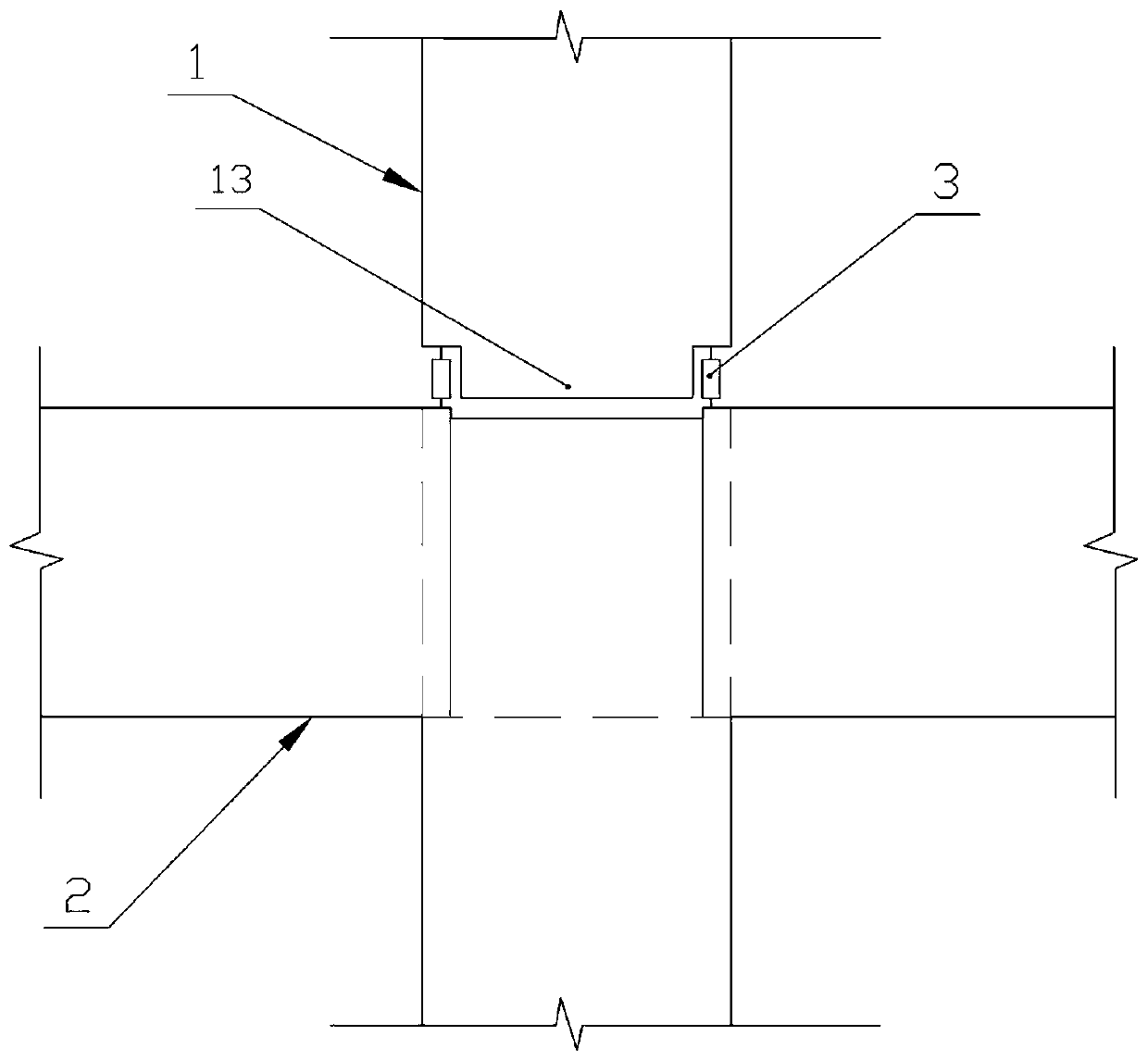
[0034] Preferred embodiment one, such as figure 1 As shown, the prefabricated concrete frame node disclosed in this embodiment includes a prefabricated column 1 and a prefabricated beam 2 , and the upper and lower prefabricated columns are connected through a threaded sleeve 3 .

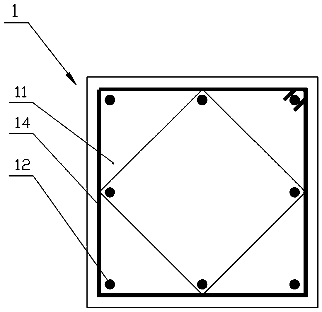
[0035] Such as figure 2 As shown, the prefabricated column 1 includes a column main body 11 and column connecting ribs 12; wherein the column main body 11 is a rectangular main body formed by pouring concrete, and the lower end of the column main body 11 is provided with a protruding core tenon 13 to facilitate the positioning of the prefabricated column when connecting The column connecting rib 12 is the steel bar that both ends are rolled with straight threads, the column connecting rib is arranged along the length direction of the column main body, and is separately located around the column main body, each edge connecting rib of the column main body is arranged along the column height and the le...

Embodiment 2

[0044] Preferred embodiment two, such as Figure 5 As shown, the difference between this embodiment and the preferred embodiment 1 is that the steel column foot 4 is used instead of the threaded sleeve 3 as the connecting piece between the upper and lower prefabricated columns.

[0045] Such as Figure 5 , Figure 6 As shown, the steel column foot 4 includes a top plate 41, a bottom plate 42 and a rib 43, and each rib is arranged in a well-shaped shape and is arranged between the top plate and the bottom plate. The ribs separate several independent areas on the top plate and the bottom plate. Each area There are connecting holes inside, and the column feet are welded in the factory. When assembling, the end (threaded) of the column connecting rib passes through the connecting hole and then tightened by a nut.

[0046] Compared with sleeve grouting, the present invention has the following advantages:

[0047] (1) Convenient processing and simple operation;

[0048] (2) The...


PUM


Abstract

The invention discloses a fabricated concrete frame joint and a construction method thereof. The fabricated concrete frame joint comprises prefabricated columns and prefabricated beams; each prefabricated column comprises a column main body and a column connecting rib, the outer ends of the column connecting ribs extend out of the column main bodies, the two adjacent prefabricated columns are arranged in an up-down alignment mode, and the column connecting ribs at the corresponding positions are connected; and the prefabricated beams are connected to the column connecting ribs exposed at the tops of the lower prefabricated columns. During construction, the lower prefabricated columns are arranged firstly, the prefabricated beams are hoisted to the tops of the lower prefabricated columns, the exposed beam connecting ribs and the column connecting ribs are bound into a cast-in-place area through stirrups, concrete is poured into the cast-in-place area, core-tenon inserting holes are reserved, and it is ensured that the tops of the column connecting ribs are exposed; the upper prefabricated columns are hoisted to the lower prefabricated columns, and the corresponding column connectingribs are connected through threaded sleeves or steel column legs; and concrete is poured for curing after steel bar joints are subjected to formwork erecting. Components are prefabricated parts whichare simple in structure and low in cost and have no influence on other construction, the construction process is convenient, the connecting mode is simple and reliable, and the construction quality is guaranteed.

Description

technical field [0001] The invention belongs to the technical field of prefabricated buildings, and in particular relates to a prefabricated concrete frame node and a construction method thereof. Background technique [0002] Prefabricated assembly technology has the advantages of high degree of mechanization, high labor utilization rate, low energy consumption, controllable cost and quality, etc., and the connection performance between prefabricated components is the key to the safety of prefabricated structures, which has attracted extensive attention. [0003] Prefabricated buildings are buildings that are prefabricated and connected on site. Therefore, the connection performance between prefabricated components is the key to the quality and safety of prefabricated buildings. Therefore, the connection of prefabricated components has received extensive attention. At present, the connection method of prefabricated reinforced concrete column reinforcement is widely used in s...

Claims


Application Information

Patent Timeline
Patent Type & Authority Applications(China)
IPC IPC(8): E04B1/21E04B1/20
CPCE04B1/20E04B1/21
Inventor 陈伯望刘芳刘哲王柳谢亚孜
Owner CENTRAL SOUTH UNIVERSITY OF FORESTRY AND TECHNOLOGY
Learn More