
Water taking end stabilizing structure and seawater pipeline system with same

A technology for stabilizing the structure and water intake pipes, which is applied in the directions of ocean energy power generation, pipeline laying and maintenance, pipes/pipe joints/pipe fittings, etc. It has not been greatly improved and other problems, to achieve the effect of weakening mutual transmission, increasing the amount of filtration, and improving stability

Pending Publication Date: 2020-02-21
TIANJIN UNIV
View PDF0 Cites 0 Cited by
  • Summary
  • Abstract
  • Description
  • Claims
  • Application Information

AI Technical Summary

Problems solved by technology

Although the in-situ stability control measures of gravity anchors and buoyancy blocks limit the large swing of the pipeline to a certain extent, they cannot completely restrain the water intake of the cold water pipe. Under the action of various loads in the ocean, the pipeline still has a large degree of freedom, its in-situ stability has not been greatly improved
[0005] Therefore, aiming at the problem of excessive freedom of the intake end of the riser pipe of the ocean temperature difference energy generation and overcoming the shortcomings of existing protective measures, the present invention proposes a U-shaped laying form of the ocean temperature difference energy cold water pipe and a multi-functional gravity block. On-site stability control structure of water intake end of standpipe for thermal energy generation

Method used


Image

  • Water taking end stabilizing structure and seawater pipeline system with same
  • Water taking end stabilizing structure and seawater pipeline system with same
  • Water taking end stabilizing structure and seawater pipeline system with same

Examples


Embodiment

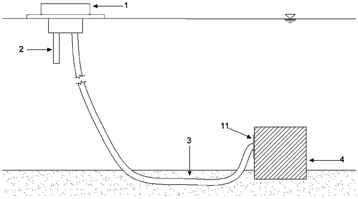
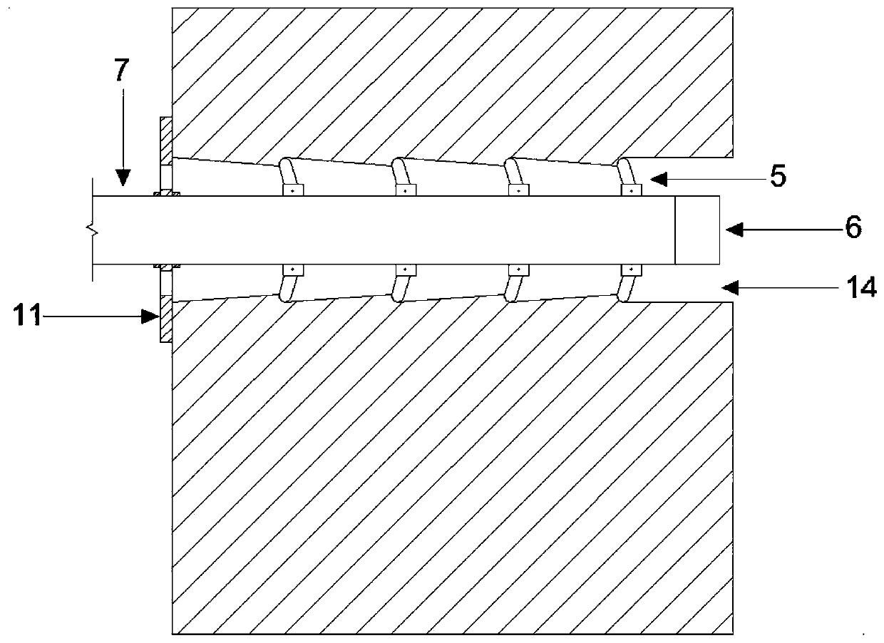
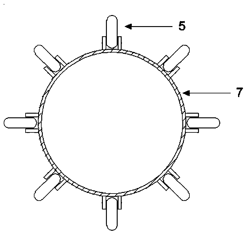
[0044] According to the present invention, a seawater pipeline system including a stable structure at the water intake end is mainly composed of a multifunctional gravity block and a U-shaped water intake pipe laying form, such as figure 1 shown. The multifunctional gravity block lifts the pipeline away from the seabed to the water intake depth. The embedding depth of the multifunctional gravity block is determined by factors such as the strength of the seabed soil and the force balance of the gravity block, so as to keep the gravity block and the water intake end of the pipeline stable. Sex is the best depth. The size of the multifunctional gravity block is determined by factors such as the diameter of the water intake pipe, the depth of water intake, the embedment depth of the gravity block, and the load on the water intake pipe. The optimal size is to ensure the stability of the water intake end of the pipeline and the gravity block itself. The height of the hole (stepped ...


PUM


Abstract

The inventio discloses a water taking end stabilizing structure and a seawater pipeline system with the water taking end stabilizing structure. A water taking stand pipe is lifted to leave the seabedto the water taking depth through a gravity block, and it is avoided that a water taking opening is in contact with the seabed to take water from the surface of the seabed, much sediment is sucked in,and the filtering amount of a water taking end filter is increased. A negative displacement limiter and a positive displacement limiting pad are combined to limit the axial displacement of a pipeline, the pipeline and the gravity block are combined, and the water taking pipe is prevented from being separated from the gravity block under the action of ocean current and waves. Wide-range swings ofthe water taking end of the pipeline is limited under the action of the gravity of the gravity block, the in-place stability of a water taking opening of the pipeline is controlled, and the scouring action of the ocean current and the waves on the water taking end of the stand pipe is reduced. By means of a buried linear pipe section, the overall stability of the water taking pipe is improved, theburied section pipeline is protected against the scouring action of the ocean current and the waves, the connected pipe sections on the two sides of the linear pipe section are separated, mutual transferring of vibration loads is weakened, and the stability of the deep seawater taking pipeline is improved.

Description

technical field [0001] The invention belongs to the technical field of ocean engineering, and in particular relates to a stable structure of a water intake end and a seawater pipeline system including the structure. Background technique [0002] In 1881, J.D'Arsonval of France first proposed the idea of ​​generating electricity by ocean temperature difference. That is to use the temperature difference between the surface layer and the deep layer of seawater to generate electricity. However, for a long period of time afterwards, due to the relatively small power of ocean temperature difference power generation, the development once stagnated. In recent years, with the sharp rise of global crude oil prices and the increasing environmental pollution, it is imminent to develop a clean and renewable energy source. Therefore, ocean temperature difference power generation has once again become a hot spot in the scientific community. [0003] In the process of using ocean temperat...

Claims


Application Information

Patent Timeline
Patent Type & Authority Applications(China)
IPC IPC(8): F16L1/12F16L1/20F03G7/05
CPCF16L1/123F16L1/20F03G7/05Y02E10/30
Inventor 刘润李青欣李成凤
Owner TIANJIN UNIV
Learn More