Chip mounter suction nozzle inspection device

A technology for inspection equipment and placement machines, applied in the direction of measuring the increase and deceleration rate of fluids, measuring devices, instruments, etc., can solve the problems that manual inspection cannot guarantee that there will be no missing inspection, and achieve small footprint and magnification Tuned, easy-to-control effects

Pending Publication Date: 2020-02-21
NANJING PANDA ELECTRONICS MFG
View PDF0 Cites 3 Cited by
  • Summary
  • Abstract
  • Description
  • Claims
  • Application Information

AI Technical Summary

Problems solved by technology

[0003] The purpose of the present invention is to propose a nozzle inspection device that can adapt to rapid detection, easy to control, convenient to pick and place, and automatically prompt whether it is defective or not, aiming at the requirement that the existing manual inspection cannot guarantee that there will be no missing inspection.

Method used


Image

  • Chip mounter suction nozzle inspection device
  • Chip mounter suction nozzle inspection device
  • Chip mounter suction nozzle inspection device

Examples


Embodiment 1

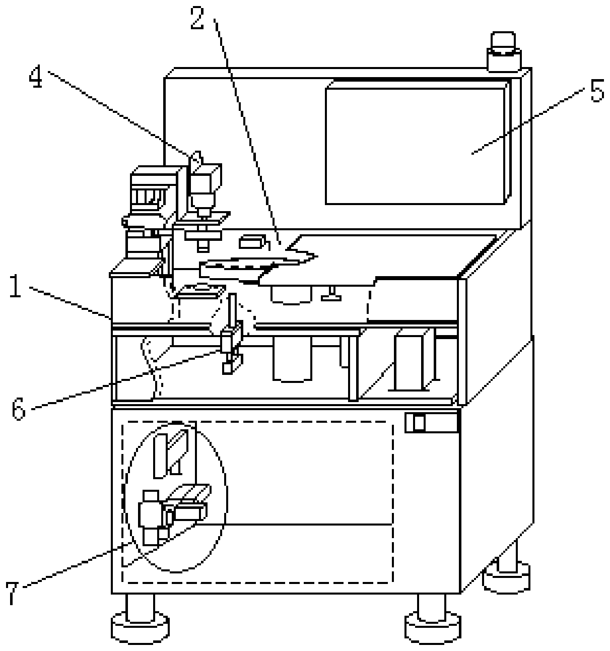
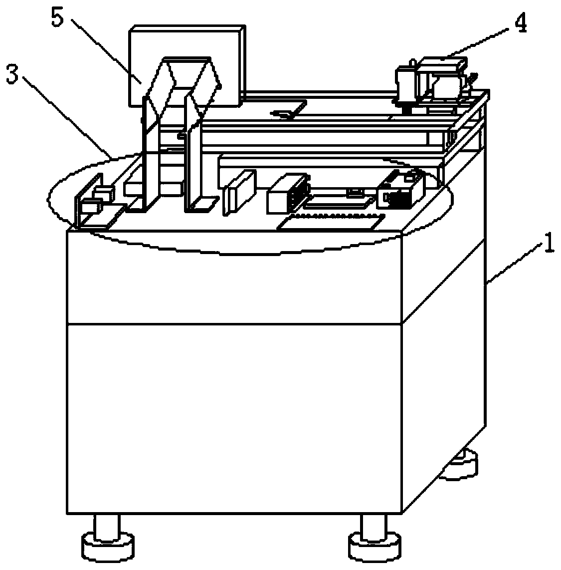
[0025] A pick and place machine nozzle inspection equipment, such as figure 1 , 2 As shown, it includes a body frame 1 , a rotating platform device 2 , an electrical control device 3 , a high-definition image capture device 4 , an integrated computer 5 , a vacuum detection device 6 , and an intake valve and wiring control device 7 . The rotary platform device 2 and the vacuum detection device 6 are all connected to the electrical control device 3 , the electrical control device 3 and the high-definition image capture device 4 are all connected to the integrated computer 5 , the rotary platform device 2 , the electrical control device 3 , and the high-definition video capture device 4 , The integrated computer 5 and the vacuum detection device 6 are all connected with the intake valve and the wiring control device 7 .

[0026] Among them, the main body frame 1 is divided into an upper compartment, a middle compartment and a lower compartment. A push-pull cover is arranged betw...


PUM


Abstract

The invention provides a chip mounter suction nozzle inspection device. The chip mounter suction nozzle inspection device comprises a body frame, a rotary platform device, an electrical control device, a high-definition image shooting device, an integrated computer, a vacuum detection device, an air inlet valve and a wiring control device, wherein a push-pull type cover plate is arranged between an upper interlayer and a middle interlayer of the body frame, and the integrated computer and the high-definition image shooting device are mounted on the upper interlayer; the middle interlayer is divided into a front part and a rear part by a partition plate, and the rotary platform device and the electrical control device are mounted on the front part and the rear part of the middle interlayerrespectively; the vacuum detection device is mounted below a rotary platform; the air inlet valve and the wiring control device are fixedly mounted on a side plate of a lower interlayer through screws. The chip mounter suction nozzle inspection device adopts a frame structure, is easy to control, convenient to take and place, stable in operation and high in precision, can clearly display the surface condition of a suction nozzle opening, detects the condition of a through hole in a suction nozzle, and can achieve vacuum degree detection on the suction nozzle.

Description

technical field [0001] The invention belongs to the field of mechanical equipment, in particular to a suction nozzle inspection device of a placement machine. Background technique [0002] As we all know, the placement machine of the patch production line sucks the components through the suction nozzle and then mounts them on the printed circuit board. The suction nozzle is a component that directly contacts the components. Whether the suction nozzle is good or not directly affects the placement quality. The machine comes with a vacuum degree inspection of the suction nozzle, but there is no special self-inspection for the condition of the front end of the suction nozzle. Cracks, contamination, gaps and other problems at the front end of the suction nozzle cannot be detected. Moreover, the front end of the commonly used nozzle is only 0.6*0.6mm, which is very small, and the naked eye cannot guarantee that it will not be missed. The use of defective nozzles may cause material...

Claims


Application Information

Patent Timeline
Patent Type & Authority Applications(China)
IPC IPC(8): G01M3/26G01N21/88G01B11/00
CPCG01B11/00G01M3/26G01N21/88
Inventor 冯恩忠毛寅生孙佳佳马旭东王斌
Owner NANJING PANDA ELECTRONICS MFG
Why Eureka
Try Eureka