Optical lens for projection

An optical lens and projection technology, applied in the field of optical lens for ultra-short-focus projection, can solve the problems of poor peripheral image quality, large angular distortion, large axial chromatic aberration, etc., to achieve improved efficiency, high peripheral brightness ratio, and guaranteed image quality Effect

Pending Publication Date: 2020-02-21
JIAXING ZHONGRUN OPTICAL TECH
View PDF0 Cites 8 Cited by
  • Summary
  • Abstract
  • Description
  • Claims
  • Application Information

AI Technical Summary

Problems solved by technology

[0002] At present, projectors have been widely used, such as the education industry. The optical lens for projection is the core module of the projector, but there are usually large spherical aberration, poor peripheral image quality, large length, greater angle, greater distortion, astigmatism and Insufficiencies such as large axial chromatic aberration, such as:

Method used


Image

  • Optical lens for projection
  • Optical lens for projection
  • Optical lens for projection

Examples


Embodiment 1

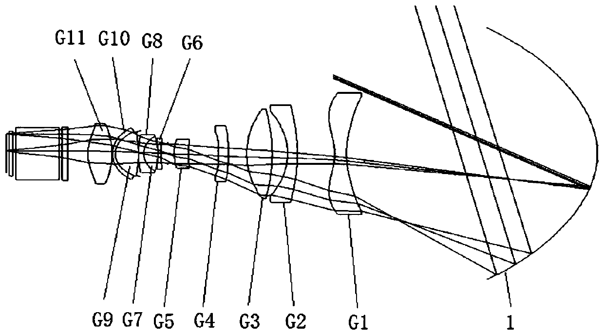
[0031] figure 1 A schematic diagram of the structure of the optical lens for projection according to Embodiment 1 of the present invention is given, such as figure 1 As shown, the optical lens for projection includes:

[0032] A concave mirror 1 arranged in order from the object side to the image side, a fixed first lens group with negative refractive power, a positive refractive power moving forward and reverse along the optical axis of the projection optical lens The second lens group, the third lens group with positive refractive power, and the galvanometer. The third lens group can be fixedly set, preferably, the third lens group can also be set movable, which can be used to adjust the distance between the sensor and the sensor, that is, adaptive adjustment and the distance between the image planes, and the adjustment range is very small. The third lens group includes at least two lenses, and the diaphragm is disposed between the lenses of the third lens group.

[0033]...

Embodiment 2

[0048] An application example of the projection optical lens according to Embodiment 1 of the present invention.

[0049] like figure 1 shown, in this application example;

[0050] The reflective surface of the concave mirror 1 is an aspherical surface; the first lens group includes a first aspherical lens G1, f 1 ∈[-35mm,-25mm].

[0051] The second lens group includes:

[0052] Lenses G2-G4 with negative, positive and negative refractive powers arranged in turn from the object side to the image side along the optical axis direction, wherein the lens G4 adjacent to the diaphragm is the third aspherical lens;

[0053] The third lens group includes:

[0054] Lenses G5-G11 with positive, negative, positive, negative, positive, negative and positive refractive powers set in turn from the object side to the image side along the optical axis direction, wherein: the lens G11 adjacent to the galvanometer is the second aspherical surface Lenses; lenses G6-G8 are triplet lens group...

Embodiment 3

[0062] An application example of the projection optical lens according to Embodiment 1 of the present invention.

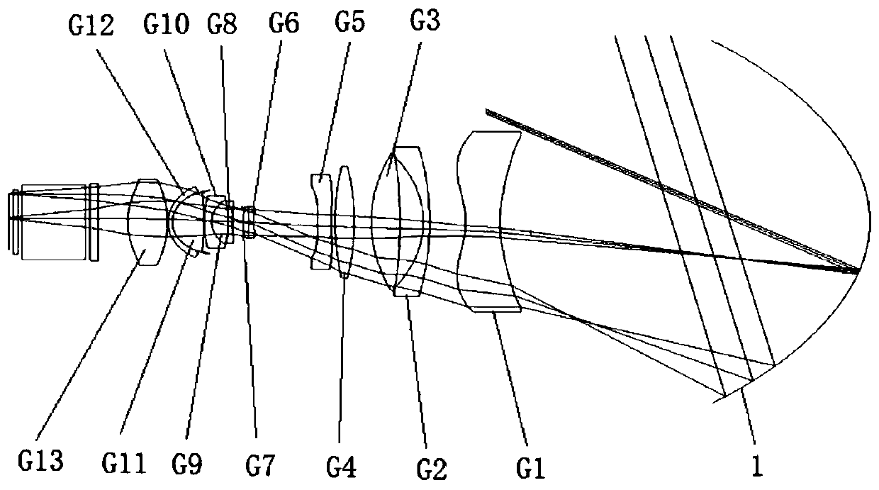
[0063] like figure 2 shown, in this application example;

[0064] The reflective surface of the concave mirror 1 is an aspherical surface;

[0065] The first lens group includes first aspherical lenses G1, f 1 ∈[-35mm,-25mm].

[0066] The second lens group includes:

[0067] along the optical axis direction from the object side to the image side, the lenses G2-G5 are respectively negative, positive, positive and negative, wherein the lens G5 adjacent to the diaphragm is the third aspherical lens;

[0068] The third lens group includes:

[0069] Along the optical axis direction from the object side to the image side, the refractive powers are respectively negative, positive, negative, positive, negative, positive, negative and positive lenses G6-G13, wherein: the lens G13 adjacent to the galvanometer is the second Aspherical lenses, lenses G6-G7 are a cement...


PUM


Abstract

The invention provides an optical lens for projection. The optical lens comprises a concave reflector, a first lens group with negative focal power, a second lens group , a third lens group having positive focal power, and a galvanometer that are arranged successively from an object side to an image side. The second lens group having positive focal power moves forwards and backwards along the optical axis of the optical lens for projection. The relative aperture FNo of the optical lens for projection satisfies the following formula I: FNo belongs to [1.8, 2.2]; and a focal length f2 of the mobile lens group and a focal length f of the optical lens for projection satisfy a formula II. The optical lens has advantages of having no distortion at a large angle, having large aperture, realizingtelecentric image space, and realizing 4K imaging and the like.

Description

technical field [0001] The present invention relates to an optical lens, in particular to an optical lens for ultra-short-focus projection. Background technique [0002] At present, projectors have been widely used, such as the education industry. The optical lens for projection is the core module of the projector, but there are usually large spherical aberration, poor peripheral image quality, large length, larger angle, larger distortion, astigmatism and Axial chromatic aberration is large and other deficiencies, such as: [0003] CN2018104678873 discloses a projection optical system with a large projection range, which specifically includes: a first lens group stationary relative to the DMD chip is arranged between a DMD chip and a reflector, the optical power of the first lens group is negative, the DMD chip and A second lens group that can move between the first lens groups of the DMD chip is arranged between the first lens groups, the second lens group has a positive ...

Claims


Application Information

Patent Timeline
Patent Type & Authority Applications(China)
IPC IPC(8): G02B13/00G02B13/06G02B13/18G02B13/22G03B21/14
CPCG02B13/0045G02B13/006G02B13/0065G02B13/06G02B13/18G02B13/22G03B21/142
Inventor 张云涛尚洁阳张平华蔡源龙
Owner JIAXING ZHONGRUN OPTICAL TECH
Why Eureka
Try Eureka