Embedded airborne infrared image visual navigation positioning method

An infrared image and visual navigation technology, applied in the field of unmanned aerial vehicles, can solve the problems of small detection angle, low flying height, and easy to be affected by building occlusion, achieve high-frequency noise suppression, improve positioning coordinates, and reliably extract targets. Effect

Pending Publication Date: 2020-02-21
NANJING XINWEIFENG DEFENSE CO LTD
View PDF4 Cites 1 Cited by
  • Summary
  • Abstract
  • Description
  • Claims
  • Application Information

AI Technical Summary

Problems solved by technology

But for the ground-based platform or the vehicle-mounted platform, there are two disadvantages: 1) Since the Heifei UAV generally flies at a low altitude, when performing long-distance detection, the detection formed by the Heifei UAV and various detection systems The angle is very small and is easily affected by building occlusion, so the detection distance of the detection system based on the ground-based or vehicle-mounted platform is very limited; 2) When detecting and positioning based on the ground-based platform or vehicle-mounted platform, it is necessary to measure the pitch of the Heifei UAV at the same time 3) A single ground-based passive reconnaissance detection system can only find direction and cannot locate, and multiple ground-based passive reconnaissance systems can locate, but the deployment of stations is inconvenient and the application scenarios are limited

Method used


Image

  • Embedded airborne infrared image visual navigation positioning method
  • Embedded airborne infrared image visual navigation positioning method
  • Embedded airborne infrared image visual navigation positioning method

Examples


Embodiment Construction

[0033] The technical solutions in the embodiments of the present invention will be clearly and completely described below in conjunction with the accompanying drawings in the embodiments of the present invention. Apparently, the described embodiments are only some of the embodiments of the present invention, but not all of them. Based on the embodiments of the present invention, all other embodiments obtained by persons of ordinary skill in the art without making creative efforts belong to the protection scope of the present invention.

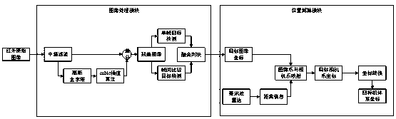
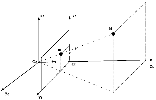
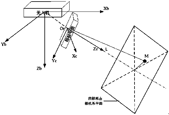
[0034] see Figure 1-3 , the present invention provides a kind of technical scheme: a kind of embedded airborne infrared image visual navigation positioning method, comprises the following steps:

[0035] Step 1: Read the original infrared image f(x,y) collected by the camera, process the image with the background suppression algorithm, and obtain the corrected image f 1 (x,y);

[0036] Step 2: Use different detection algorithms to suppress...


PUM


Abstract

The invention discloses an embedded airborne infrared image visual navigation positioning method, which comprises the following steps of: 1, reading an infrared original image f (x, y) acquired by a camera, and processing the image by using a background suppression algorithm to obtain a corrected image f1 (x, y); 2, carrying out single-frame target detection and inter-frame target detection on thecorrected image f1 (x, y) respectively, and judging detection results comprehensively to obtain a final detection result image f2 (x, y); obtaining coordinates (xc, yc, zc) of the target point in thecamera system according to the mapping relation between the camera system and the image system and the millimeter wave radar ranging result; according to the default coordinate transformation matrixT existing between the machine system and the camera system, obtaining the coordinates (xb, yb, zb) of the target in the machine system. The method has the advantages that the image quality is improved, later positioning is facilitated, the influence of high-frequency noise is avoided, and target positioning is more accurate.

Description

technical field [0001] The invention relates to the technical field of unmanned aerial vehicles, in particular to an embedded airborne infrared image visual navigation positioning method. Background technique [0002] With the rapid development of the small drone industry, there are more and more bad cases of black flying drones threatening public safety, infringing public privacy, and interfering with major events. As a major threat source, there is an urgent need for low-altitude security. It is of great practical significance to realize early warning, defense and control through the detection and positioning of black flying drones. [0003] At present, the detection and discovery of black flying UAVs within a certain airspace is mainly based on ground or vehicle-mounted platforms. Common methods include radar detection, optical detection, sound detection, and passive reconnaissance detection. But for the ground-based platform or the vehicle-mounted platform, there are tw...

Claims


Application Information

Patent Timeline
Patent Type & Authority Applications(China)
IPC IPC(8): G06T7/00G06T5/00G06T7/11G06T7/194
CPCG06T7/0002G06T5/002G06T7/11G06T7/194G06T2207/10048G06T2207/20032
Inventor 赵伟陈旭花思齐
Owner NANJING XINWEIFENG DEFENSE CO LTD
Why Eureka
Try Eureka