Camera group calibration method and device based on global calibration frame

A calibration method and calibration frame technology, applied in image analysis, instruments, calculations, etc., can solve the problems of time-consuming and laborious, high production process and installation process requirements, inability to disassemble and modify, and achieve hardware production and installation. The effect of low process requirements and low implementation costs

Active Publication Date: 2020-02-21
TSINGHUA UNIV
View PDF7 Cites 7 Cited by
  • Summary
  • Abstract
  • Description
  • Claims
  • Application Information

AI Technical Summary

Problems solved by technology

The calibration process requires high-level personnel to carry out long-term debugging and adjustment. It has high requirements for production technology and installation technology, which is time-consuming and laborious, and cannot be disassembled and modified after leaving the factory.

Method used


Image

  • Camera group calibration method and device based on global calibration frame
  • Camera group calibration method and device based on global calibration frame
  • Camera group calibration method and device based on global calibration frame

Examples


Embodiment Construction

[0042] Embodiments of the present invention are described in detail below, examples of which are shown in the drawings, wherein the same or similar reference numerals designate the same or similar elements or elements having the same or similar functions throughout. The embodiments described below by referring to the figures are exemplary and are intended to explain the present invention and should not be construed as limiting the present invention.

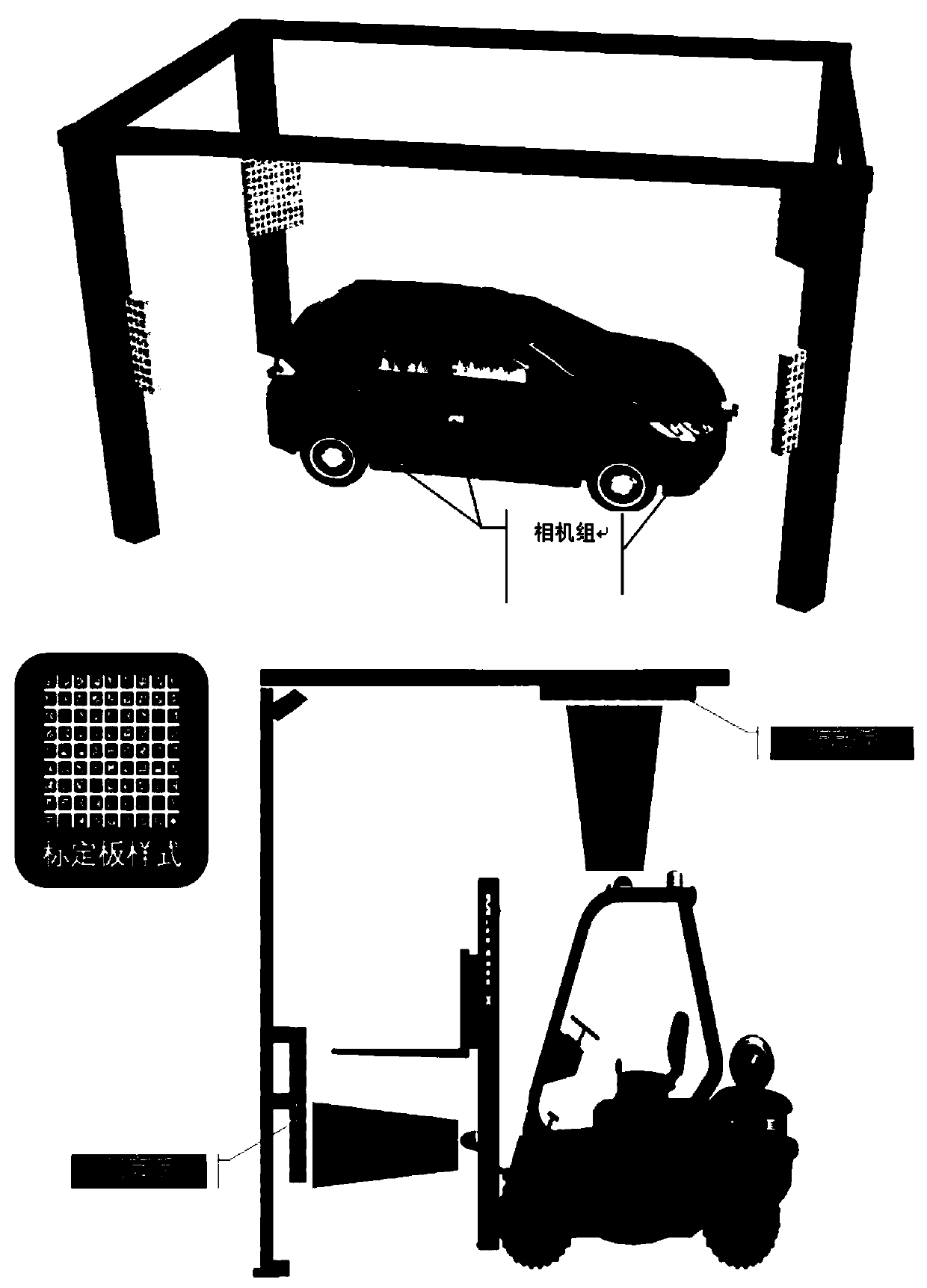
[0043] Aiming at the technical problems described in the background technology, the solution of the embodiment of the present invention is to design a global calibration frame, which contains a number of calibration plates facing the corresponding cameras, and each calibration plate contains a plurality of globally unique ID information marks, such as figure 2 As shown in , where the geometric relationship between the marks and the marks has been measured in advance when processing the calibration object. This configuration can ...


PUM


Abstract

The invention discloses a camera group calibration method and device based on a global calibration frame, and the method comprises the following steps: designing the size, ID and geometric position posture of a calibration plate for the view field range of each camera; detecting cell corner points, and obtaining an absolute pose of the camera under a calibration plate coordinate system; carrying out nonlinear optimization and coordinate system conversion according to the absolute poses of the cameras, and estimating and obtaining the relative positions and poses of the multiple cameras. According to the method, by constructing a global calibration frame, the relative positions and attitudes of a plurality of cameras are estimated, and the method has important theoretical and practical values.

Description

technical field [0001] The invention relates to the technical field of camera calibration, in particular to a camera group calibration method and device based on a global calibration frame. Background technique [0002] In recent years, smart devices with cameras (such as unmanned vehicles, drones, etc.) have shown an explosive increase, and their own positioning requirements have become more and more intense. Visual positioning technology has its own cheap and easy-to-deploy characteristics, which have the value of in-depth research. Visual positioning can be carried out in monocular and multi-purpose methods. Traditional monocular cameras usually have a limited field of view, which easily causes missing matching, and cannot solve the problem of scale uncertainty. In contrast, the multi-camera group can not only provide a wide field of view, but also constrain the scale of the construction map, which can provide more perception capabilities. But at the same time, multiple...

Claims


Application Information

Patent Timeline
Patent Type & Authority Applications(China)
IPC IPC(8): G06T7/80
CPCG06T7/85Y02T10/40
Inventor 周杰邓磊陈宝华邓杰仁吴垚垚李健于恒
Owner TSINGHUA UNIV
Why Eureka
Try Eureka