Battery charging method and system

A battery charging and battery technology, applied in the field of power electronics, can solve the problems of UPS efficiency drop, overcharge, increase internal resistance, etc., and achieve the effect of ensuring battery charging capacity, improving charging efficiency, and prolonging service life

Active Publication Date: 2020-02-21
DELTA ELECTRONICS INC
View PDF16 Cites 1 Cited by
  • Summary
  • Abstract
  • Description
  • Claims
  • Application Information

AI Technical Summary

Problems solved by technology

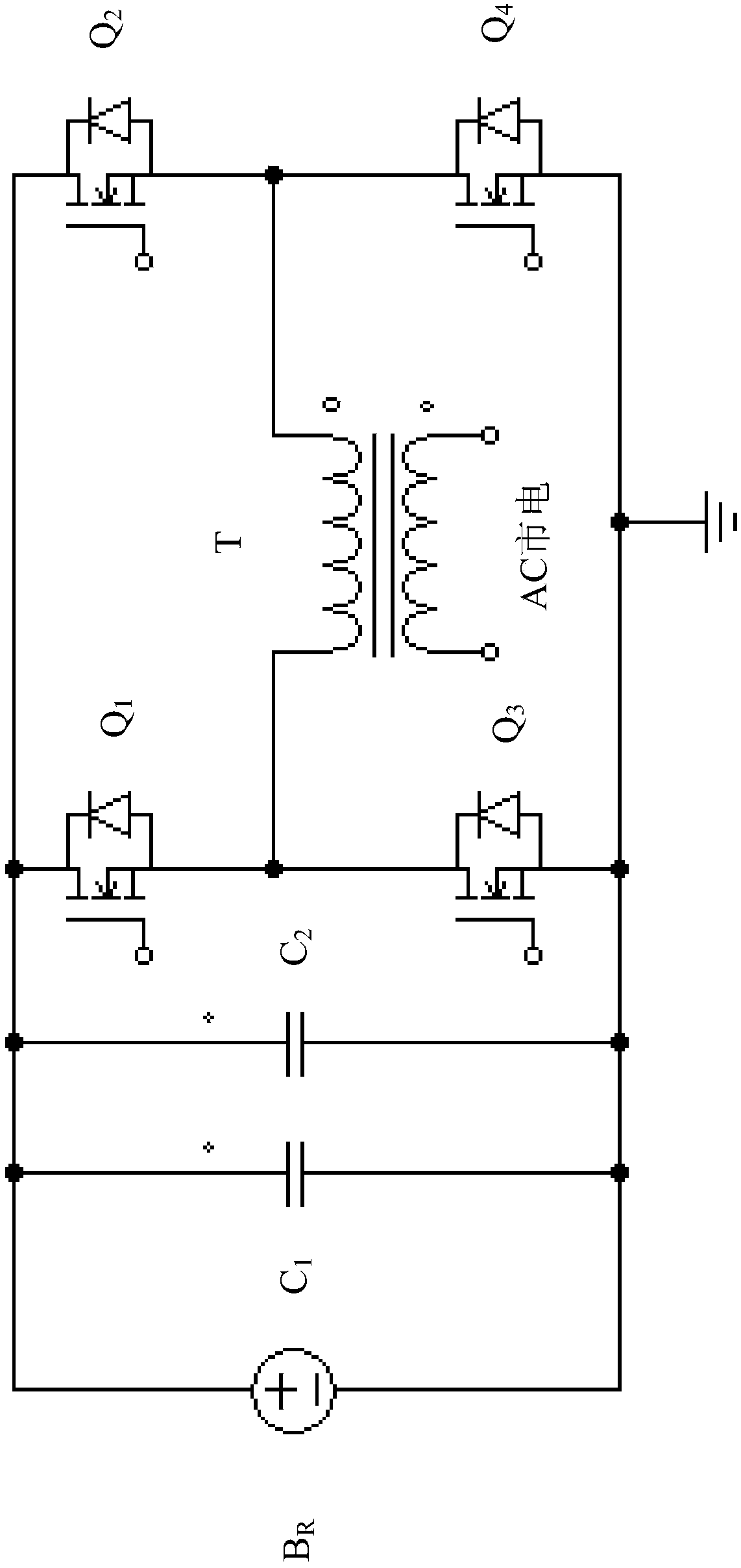
[0006]1. Since the switching tubes Q3 and Q4 are controlled by a fixed duty cycle for constant voltage Charging, so the current is too large at the initial stage of charging, which will easily cause the plate of the battery BR to vulcanize
[0007]2. Since the UPS is put into operation when the AC mains power is cut off, the battery BR will not be fully charged and discharged state
In this way, the long-term use of the battery BR will cause the electrolyte in the plate to be difficult to decompose, eventually producing lead sulfate, which increases the internal resistance of the battery BR
In addition, the traditional UPS charging method cannot adjust the charging voltage according to the internal resistance of the battery BR, and cannot desulfurize the vulcanized battery BR
[0008]3. Since there is no floating charging mechanism for the later stage of charging, or the floating charging is always maintained, and the power supply of the UPS control board circuit is provided by the battery BR , so that if the battery BR is not charged for a long time, it will cause the battery BR to be over-discharged, or because the battery BR has been In the state of floating charge, it will cause the battery BR to be overcharged, which will reduce the efficiency of the UPS or cause problems such as temperature rise

Method used


Image

  • Battery charging method and system
  • Battery charging method and system
  • Battery charging method and system

Examples


Embodiment Construction

[0048] Example embodiments will now be described more fully with reference to the accompanying drawings. Example embodiments may, however, be embodied in many forms and should not be construed as limited to the embodiments set forth herein; rather, these embodiments are provided so that this disclosure will be thorough and complete, and will fully convey the concept of example embodiments to those skilled in the art. The same reference numerals in the drawings denote the same or similar structures, and thus their detailed descriptions will be omitted.

[0049] Furthermore, the described features, structures, or characteristics may be combined in any suitable manner in one or more embodiments. In the following description, numerous specific details are provided in order to give a thorough understanding of embodiments of the invention. However, those skilled in the art will appreciate that the technical solutions of the present invention may be practiced without one or more of...


PUM


Abstract

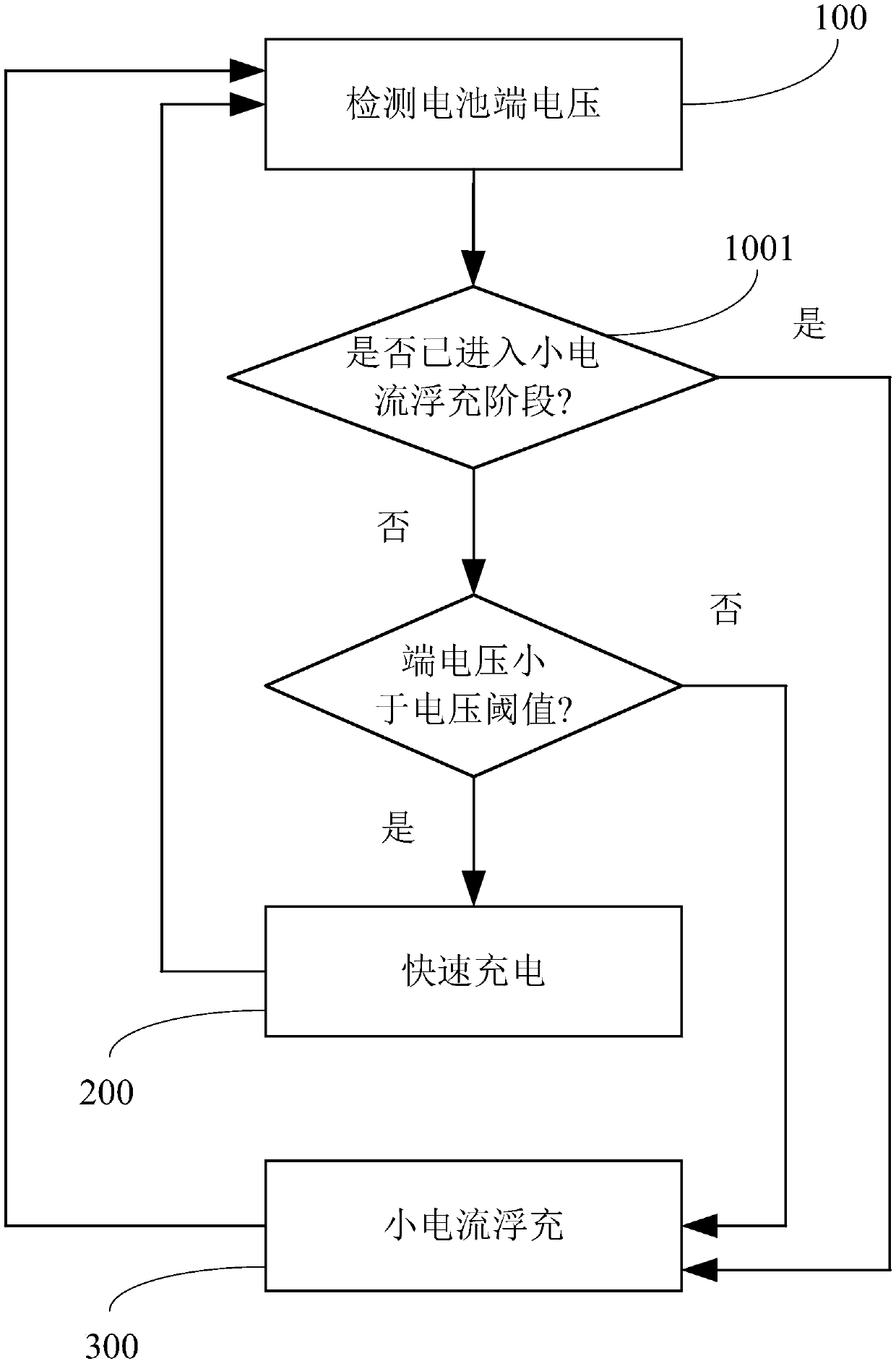
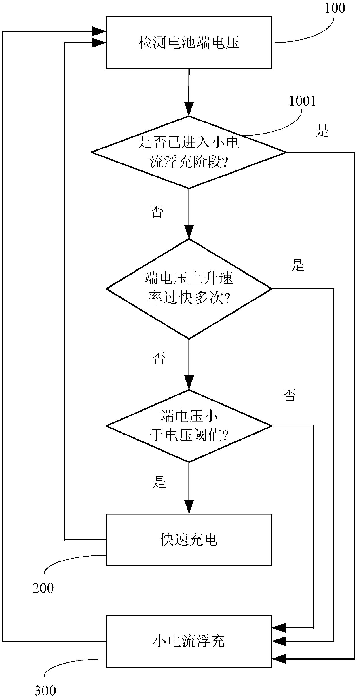
The invention provides a battery charging method. The method comprises steps that a terminal voltage of a battery is detected; when the terminal voltage is smaller than a voltage threshold value, a rapid charging step is performed, the rapid charging step comprises steps of calculating a rising rate of the terminal voltage, comparing the rising rate with a rising rate reference value, and controlling the terminal voltage according to the comparison result; when the terminal voltage is not less than the voltage threshold, a low-current floating charging step is performed, and the low-current floating charging step comprises steps of charging the battery at intervals in a preset floating charging period, calculating a descending rate of the terminal voltage in a first time interval of the floating charging period, comparing the descending rate with a descending rate reference value, controlling the terminal voltage according to a comparison result, and stopping charging in a second timeinterval of the floating charging period. The method is advantaged in that the charging current can be controlled only by sampling the voltage at a battery end, battery charging efficiency can be effectively improved, loss of the whole system is reduced, the battery charging amount is effectively ensured, overcharging does not occur, and the service life of the battery can be prolonged.

Description

technical field [0001] The invention relates to the technical field of power electronics, in particular to a battery charging method and a battery charging system using the battery charging method. Background technique [0002] The uninterruptible power supply (UPS) charges the battery when the mains input is normal, and immediately converts the DC power of the battery into 220V AC to supply power to the load when the mains is interrupted. [0003] figure 1 It is a schematic diagram of a battery charging circuit in the prior art. Such as figure 1 As shown in , the battery charging circuit in the prior art usually includes: a filter capacitor C 1 and C 2 , connected in parallel in a battery B R Both ends of the battery B R There is a DC voltage across both terminals, that is, the terminal voltage U DC ; by the switch tube Q 1 , Q 2 , Q 3 and Q 4 Composed of inverter / rectifier, its DC terminal is connected in parallel with battery B R The two ends of the transforme...

Claims


Application Information

Patent Timeline
Patent Type & Authority Applications(China)
IPC IPC(8): H01M10/42H01M10/44H02J7/06H02J7/10
CPCH01M10/446H01M10/4242H02J7/06H02J9/04H02J7/007182H02J7/00711H01M10/44H01M10/425H01M2010/4271H01M2220/10Y02E60/10H01M10/06H02J7/00712
Inventor 熊亮刘臻基徐文康
Owner DELTA ELECTRONICS INC
Why Eureka
Try Eureka