Live lead clip

A technology of wire clips and wire clips, applied in the direction of electrical connection seat, connection, circuit, etc., can solve the problems of inability to install the insulating rod, troublesome installation of C-type wire clips, and provide elastic deformation, so as to prevent damage caused by excessive locking. , The effect of excellent connection performance and low cost

Pending Publication Date: 2020-02-21
JIANGSU ELECTRIC POWER CO +1
View PDF0 Cites 2 Cited by
  • Summary
  • Abstract
  • Description
  • Claims
  • Application Information

AI Technical Summary

Problems solved by technology

[0003] At present, the commonly used live wire clamps for 10kV distribution network mainly include: bolt J-type wire clamps, bolt C-type wire clamps and ejection wedge-shaped wire clamps. Among them: First, the bolt J-type wire clamps are composed of two J Formed element and a connecting bolt, through the longitudinal fastening force of the bolt, the wedges of the upper and lower J elements are wedged into each other, and the main transmission line and the drainage line are clamped at the same time, and the main transmission line and the drainage line are realized by the J-shaped clamp. The advantage of the electrical conduction between the bolts is that the longitudinal fastening force of the bolt and the force acting on the wire laterally by the two J elements do not interfere with each other. The problem is that the existing J-shaped clamps are generally made of cast non-elastic materials, which cannot provide elastic deformation after installation. At the same time, due to the limitation of the overall length of the clamp, there will be heat generation in the heavy-load line after connection. , so that its reliability is greatly affected; secondly, the bolt C-type clamp is composed of 1 C-shaped element, 2 hinged wedges and 1 bolt, and the left and right sides are hinged by the longitudinal fastening force of the bolt. The wedge is wedged into the groove of the C-shaped component to clamp the main power transmission line and the drain wire respectively and realize the electrical connection. Its advantage is that the connection performance is better, which is limited by the small opening of the C-shaped component and the hinged wedge can be separated and moved. Flexibility leads to troublesome installation of C-type clamps, and the installation operation cannot be performed with insulating rods
Third, the ejection wedge-shaped clamp is composed of a C-shaped element for bonding the main power transmission line and the drain line and a wedge for fastening, and is equipped with a special ejection installation tool (including ejection chip), the installation operation When using the hitting installation tool to trigger the ejection impact force generated by the gunpowder combustion inside the ejection core, the wedge is pressed into the C-shaped element to realize the electrical connection between the main power transmission line and the drain line wire. The advantage is that there is no need to worry about the contact caused by the reduction of the component fastening force The resistance increases, and due to the greater fastening force of the clamp after ejection, the flow capacity of the wedge-shaped clamp is much higher than that of other clamps, but its problems are: high cost and indirect operation

Method used


Image

  • Live lead clip
  • Live lead clip
  • Live lead clip

Examples


Embodiment 1)

[0026] In this embodiment, when describing the orientation, the figure 1 The direction facing is the front in the description, with the back facing figure 1 The direction it is facing is the rear in the description, figure 1 The up and down, left and right directions of are still the up and down, left and right directions in the description.

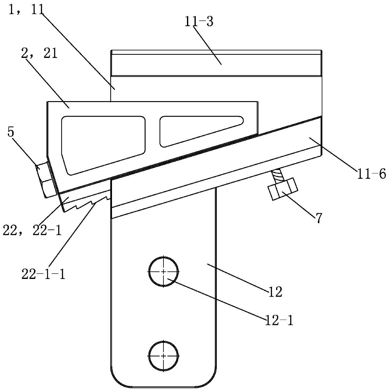
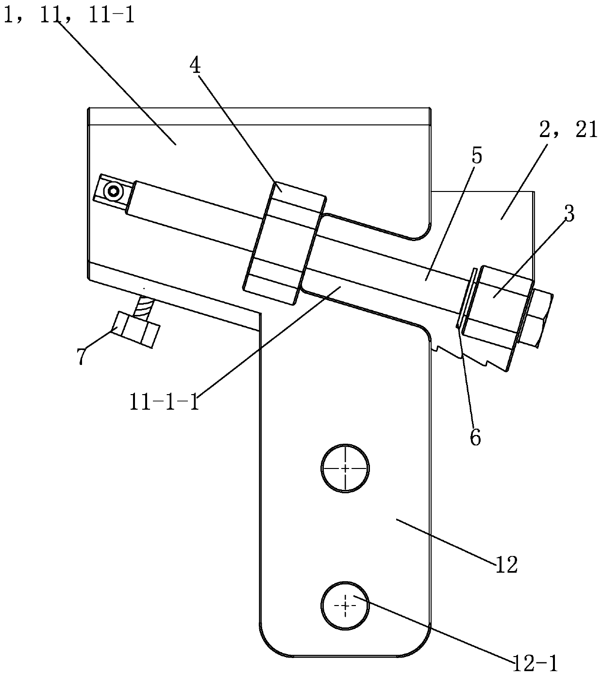
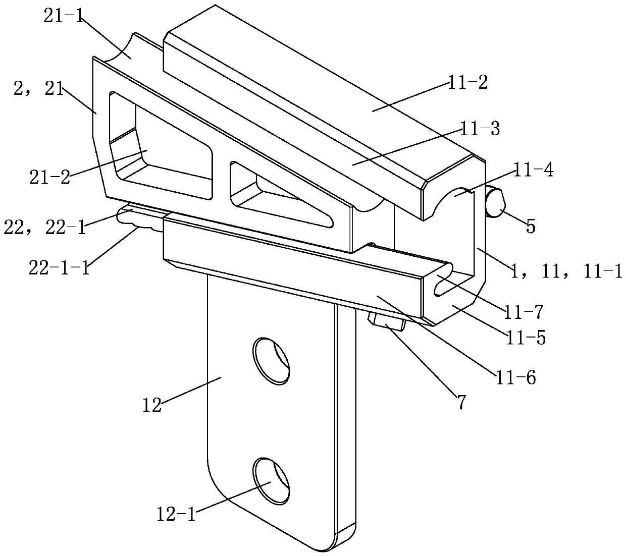
[0027] See Figure 1 to Figure 4 , The live lead clamp of this embodiment is mainly composed of a main body 1, a clamp slider 2, a first nut 3, a second nut 4, a driving bolt 5, a retaining ring 6 and a non-return bolt 7.

[0028]The main body 1 is mainly composed of a wire clamping portion 11 on the upper side and a drain wire connecting portion 12 on the lower side. The wire clamping portion 11 is mainly composed of a rear plate 11-1, an upper plate 11-2, an upper front side plate 11-3, a lower plate 11-5, a lower front side plate 11-6 and a sliding sleeve plate 11-7; The plate 11-1 is an overall wedge-shaped plate body whose left ...


PUM


Abstract

The invention provides a live lead clip which includes a main body, a wire clamping slider, a first nut, a second nut, and a driving bolt. The main body is composed of a wire clamping part which is used for clamping a wire and wedge-shaped in the whole when used, and a drainage wire connecting part which is arranged on the lower side of the wire clamping part, integrally connected with the wire clamping part and connected with a drainage wire when in use, wherein the wire clamping part and the drainage wire connecting part are integrated. The wire clamping slider is a structural member which is in sliding fit with the wire clamping part of the main body and wedge-shaped in the whole. The first nut is fixed on the wire clamping slider. The second nut is fixed on the wire clamping part of the main body. The driving bolt is screwed with the first nut and the second nut. When the live lead clip is used, the driving bolt is screwed by an arranging tool, and the wire clamping slider can slide in the wire clamping part of the main body to clamp the wire of a power transmission line. The lead clip provided by the invention has the advantages of simple structure, low cost, convenient installation and operation during use, has the advantages of the existing similar devices, and overcomes the disadvantages of the existing similar devices.

Description

technical field [0001] The invention relates to the field of auxiliary tools for 10kV power supply lines, in particular to a live lead clamp. Background technique [0002] The 10kV distribution network is a power infrastructure that directly supplies electric energy to users. In order to improve the power supply reliability of the 10kV distribution network, the 10kV distribution network needs to be upgraded and maintained frequently. In the 10kV distribution network upgrade and operation and maintenance work, a large number of operations of lapping branch drain lines on the main transmission line are involved, and an important auxiliary tool for lapping branch drain lines on the main transmission line is the A terminal clamp that electrically connects the drain wire to the main transmission line. [0003] At present, the commonly used live wire clamps for 10kV distribution network mainly include: bolt J-type wire clamps, bolt C-type wire clamps and ejection wedge-shaped wir...

Claims


Application Information

Patent Timeline
Patent Type & Authority Applications(China)
IPC IPC(8): H01R11/26H01R13/621H01R13/639
CPCH01R11/26H01R13/6215H01R13/639
Inventor 殷洪海王峰吴彬蒋建平彭涛薛波
Owner JIANGSU ELECTRIC POWER CO
Why Eureka
Try Eureka