Power electronic transformer topology with power self-balancing capability and control method thereof

A power electronic and self-balancing technology, applied in the output power conversion device, the conversion of DC power input to DC power output, and the conversion of AC power input to AC power output, etc., can solve the problem that the topology of power electronic transformers is not mentioned or discussion, etc.

Inactive Publication Date: 2020-02-21
XI AN JIAOTONG UNIV
View PDF16 Cites 5 Cited by
  • Summary
  • Abstract
  • Description
  • Claims
  • Application Information

AI Technical Summary

Problems solved by technology

Power electronic transformer topologies capable of this functio

Method used


Image

  • Power electronic transformer topology with power self-balancing capability and control method thereof
  • Power electronic transformer topology with power self-balancing capability and control method thereof
  • Power electronic transformer topology with power self-balancing capability and control method thereof

Examples


Embodiment 1

[0059] Embodiment 1: A power electronic transformer with 10kV AC at the input side, 0.38kV three-phase four-wire AC at the output side and ±375V bipolar DC.

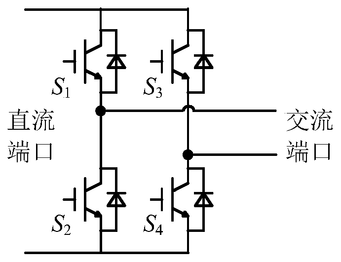
[0060] use as Figure 10 As shown in the topology, the power electronic transformer topology with power self-balancing capability includes input stage, isolation stage and output stage.

[0061] The input stage is a three-phase series H-bridge, and each phase includes N identical series-connected single-phase H-bridge converters, where N is a positive integer, connected in series to one phase of the power grid through a reactor G. The cascaded number of single-phase H-bridge converters for each phase is determined by the input voltage level and the level of selected power electronic devices. In this embodiment, the input voltage is 10kV (line voltage), the input stage is star-connected, and when the IGBT with a withstand voltage switching device of 3.3kV / 150A is selected and the DC voltage is set to 2500V, each phase in...


PUM


Abstract

The invention discloses a power electronic transformer topology with power self-balancing capability and a control method thereof. A DC port of each H-bridge converter of an input stage is connected with primary side DC ports of two dual-active full-bridge converters. The two dual-active full-bridge converters form a group, wherein the positive electrode of a secondary side DC port of a first dual-active full bridge serves as an output positive electrode of the group of dual-active full bridge converters, the negative electrode of a secondary side DC port of a second dual-active full bridge serves as an output negative electrode of the group of dual-active full bridge converters, and the negative electrode of the secondary side DC port of the first dual-active full bridge and the positiveelectrode of the secondary side DC port of the second dual-active full bridge are connected to serve as an output neutral point of the group of dual-active full bridge converters. The topology can enable a power electronic transformer to realize bipolar low-voltage DC output and three-phase four-wire system low-voltage AC output.

Description

technical field [0001] The invention belongs to the technical field of power electronic transformers, and in particular relates to a power electronic transformer topology with power self-balancing capability and a control method thereof. Background technique [0002] Traditional power transformers are simple in structure, high in efficiency and high in reliability, and are widely used in power systems. However, the low operating frequency makes the traditional transformer bulky and bulky, and mineral oil, epoxy resin, and flame retardant oil are used as insulation or cooling media, which have potential hidden dangers of fire and environmental pollution. In addition, it can usually only achieve relatively single functions such as electrical isolation, voltage level conversion, and bidirectional power transfer, but has no functions such as grid-side power quality adjustment, harmonic transfer isolation, overload and fault protection, and load voltage regulation. These weaknes...

Claims


Application Information

Patent Timeline
IPC IPC(8): H02M3/335H02M5/458H02M7/219H02M1/10
CPCH02M1/10H02M3/33523H02M3/33576H02M5/4585H02M7/219
Inventor 欧阳少迪刘进军陈晖杨跃陈星星宋曙光
Owner XI AN JIAOTONG UNIV
Why Eureka
Try Eureka