
Double-layer combined ferrite core applied to power transformer

A ferrite core and power transformer technology, applied in transformer/inductor core, transformer/inductor components, transformer/inductor coil/winding/connection, etc., can solve large eddy current loss and troublesome winding process , heat dissipation, shielding and other performance issues

Pending Publication Date: 2020-11-13
安徽中富磁电股份有限公司
View PDF7 Cites 0 Cited by
  • Summary
  • Abstract
  • Description
  • Claims
  • Application Information

AI Technical Summary

Problems solved by technology

[0002] Magnetic cores are used in coils or transformers in various electronic devices. There are many shapes and types of magnetic cores, such as C, O and E types. Different structures have different functions, even if there are subtle The difference will also cause the difference in heat dissipation, shielding and other performances. The existing ferrite cores used in circuit transformers need to be completely immersed in cooling oil to reduce the temperature of the core during operation, but the cooling oil cannot enter the magnetic core. Inside the core, the heat dissipation effect of the core is limited;
[0003] The principle of the existing transformer is to wind the coil on both sides of the magnetic core. The cross-sectional area formed by the primary coil and the secondary coil is the same, that is, the magnetic flux is the same, and the voltage transformation is realized only by the number of winding coils. The magnetic lines of force on other parts of the magnetic core are not well utilized, resulting in large eddy current losses, and most of the magnetic cores are fixed in design, and the coil is wound on the magnetic core, and the winding process is more troublesome. Therefore, a detachable upper and lower layer can be designed. It is easy to wind and can change the cross-sectional area of ​​the winding coil, and the combined ferrite core with good heat dissipation effect

Method used

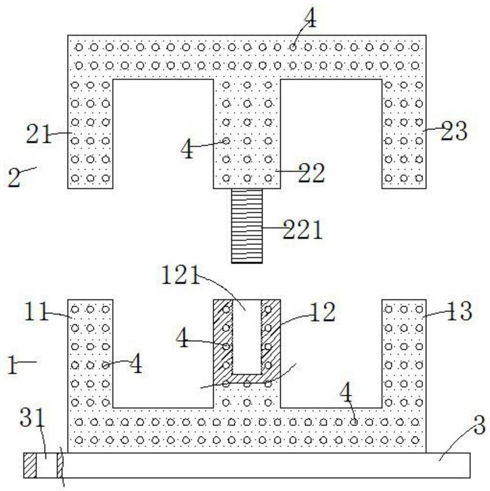
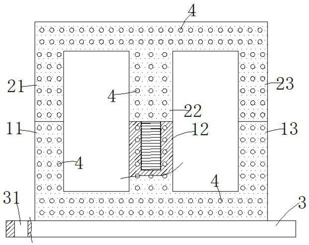
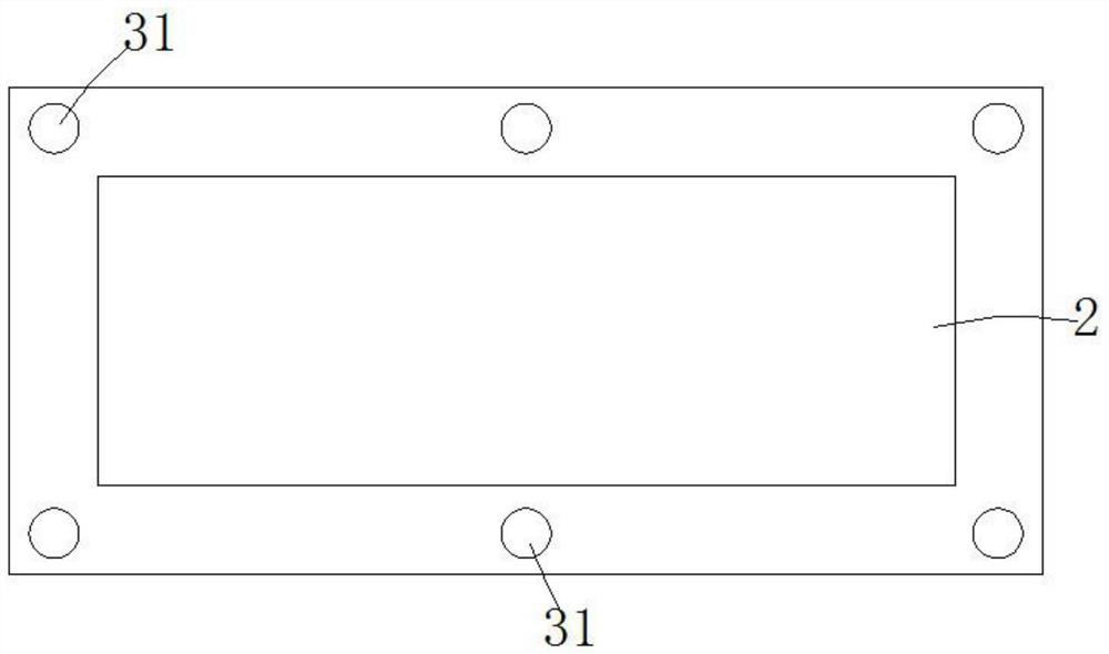

Image

  • Double-layer combined ferrite core applied to power transformer
  • Double-layer combined ferrite core applied to power transformer
  • Double-layer combined ferrite core applied to power transformer

Examples


Embodiment Construction

[0018] The present invention will be further described in detail below in conjunction with the accompanying drawings and specific embodiments. The embodiments of the present invention have been presented for purposes of illustration and description, but are not intended to be exhaustive or to limit the invention to the form disclosed. Many modifications and changes will be apparent to those of ordinary skill in the art. The embodiment was chosen and described in order to better explain the principles of the invention and the practical application, and to enable others of ordinary skill in the art to understand the invention and design various embodiments with various modifications as are suited to the particular use.

[0019] A double-layer composite ferrite core applied to power transformers, such as Figure 1-5 As shown, it includes a lower part 1 and an upper part 2 that are both in the shape of an inverted "E". The opening of the lower part 1 faces upwards, and the openin...


PUM


Abstract

The invention discloses a double-layer combined ferrite core applied to a power transformer, belongs to the technical field of magnetic cores, and mainly solves the problems that coil winding is inconvenient, magnetic lines of force cannot be fully utilized, the eddy current loss in the voltage transformation process is large, and the cooling is insufficient. The double-layer combined ferrite corecomprises an inverted E-shaped lower layer piece (1) and an inverted E-shaped upper layer piece (2), wherein the lower-layer part (1) and the upper-layer part (2) are detachably connected to facilitate coil winding, the lower-layer piece (1) comprises a lower left side column (11), a lower middle column (12) and a lower right side column (13), the upper-layer piece (2) comprises an upper left side column (21), an upper middle column (22) and an upper right side column (23), and a primary coil (5) and a secondary coil (6) are wound at different positions to form coils with different section widths so as to change output voltage. According to the invention, the coils can be conveniently wound, then the double-layer combined ferrite core is installed in the transformer, the cooling effect isgood in use, the magnetic lines of force are fully utilized, and the eddy-current loss is small.

Description

technical field [0001] The invention relates to the field of magnetic cores, and more specifically, the utility model relates to a double-layer composite ferrite core applied to a power transformer. Background technique [0002] Magnetic cores are used in coils or transformers in various electronic devices. There are many shapes and types of magnetic cores, such as C, O and E types. Different structures have different functions, even if there are subtle The difference will also cause the difference in heat dissipation, shielding and other performances. The existing ferrite cores used in circuit transformers need to be completely immersed in cooling oil to reduce the temperature of the core during operation, but the cooling oil cannot enter the magnetic core. Inside the core, the cooling effect of the core is limited; [0003] The principle of the existing transformer is to wind the coil on both sides of the magnetic core. The cross-sectional area formed by the primary coil ...

Claims


Application Information

Patent Timeline
IPC IPC(8): H01F27/26H01F27/28H01F27/30H01F27/34H01F27/12
CPCH01F27/263H01F27/306H01F27/2876H01F27/34H01F27/12H01F2027/348
Inventor 赵长宽尹君程像标
Owner 安徽中富磁电股份有限公司
Learn More