LED driver based on Sepic soft switching and hybrid driving method thereof
A technology of LED driver and hybrid drive, which is applied in the direction of instruments, electric variable adjustment, high-efficiency power electronic conversion, etc. It can solve problems affecting LED efficiency, brightness life, etc., and achieve the effect of reducing loss and constant output current
- Summary
- Abstract
- Description
- Claims
- Application Information
AI Technical Summary
Problems solved by technology
Method used
Image
Examples
specific Embodiment 1
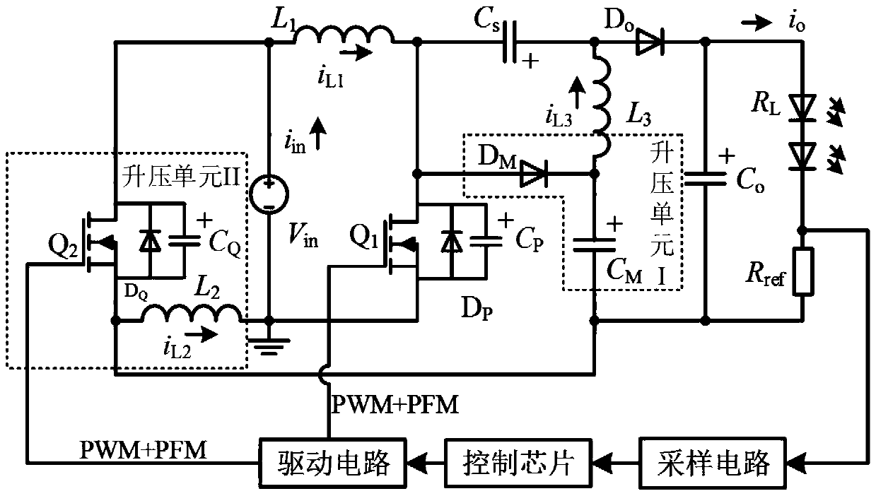
[0040] according to figure 1 As shown, the present invention provides a Sepic soft-switching LED driver. The driver includes: a sampling circuit, a control chip, a driving circuit, a boost unit I, a boost unit II, and a voltage source V in , Inductance L 1 , Switch tube Q 1 , Capacitance C P , Diode D P , Capacitance C s , Inductance L 3 , Diode D o , Output capacitor C o , Sampling resistor R ref And diode R L ;
[0041] The boost unit II includes a switch tube Q 2 , Capacitance C Q , Diode D Q And inductance L 2 , Capacitance C Q And diode D Q Parallel to switch Q 2 Both ends of the booster unit I includes a diode D M And capacitance C M ;
[0042] Voltage source V in The positive terminal is connected to the inductance L 1 One end, inductance L 1 Connect the capacitor C to the other end s And switch Q 1 One end, capacitance C s Connect diode D to the other end o And inductance L 3 One end, diode D o The other end is connected to the output capacitor C o And diode R L One end, di...
specific Embodiment 3
[0093] The input and output parameters of the converter used in the present invention under full load are: 12VVin, 120V Vout, output current 300mA, and rated switching frequency of 1MHz. From this, the drive and voltage waveforms of the switch tube under full load are obtained as Figure 7 As shown, the output voltage and current at full load are Figure 8 Shown, according to Picture 9 Under 90% load, the corresponding switch tube drive, voltage at both ends and output voltage waveform are shown. When the final load changes in the range of 100% to 75%, the dynamic waveform of the output voltage and current changes is as follows: Picture 10 Shown.
[0094] Calculate according to the specific parameters of the circuit and get Image 6 The corresponding switching frequency and duty cycle change curve under different loads in the medium, and the corresponding PWM+PFM control program is written to realize closed-loop control.
[0095] For the 1MHz high frequency DC / DC converter, the dr...
PUM
 Abstract
Description
Claims
Application Information
 - R&D
- Intellectual Property
- Life Sciences
- Materials
- Tech Scout
- Unparalleled Data Quality
- Higher Quality Content
- 60% Fewer Hallucinations
Browse by: Latest US Patents, China's latest patents, Technical Efficacy Thesaurus, Application Domain, Technology Topic, Popular Technical Reports.
© 2025 PatSnap. All rights reserved.Legal|Privacy policy|Modern Slavery Act Transparency Statement|Sitemap|About US| Contact US: help@patsnap.com


