Low-pressure filling method and device using electromagnetic stirring technology

A technology of electromagnetic stirring and electromagnetic stirrer, which is used in the filling of low-pressure casting. The low-pressure filling field using electromagnetic stirring technology can solve the problem that the molten metal cannot fill the cavity, reduce the metal utilization rate of castings, and affect the mechanical properties of castings, etc. problems, to achieve the effect of increasing metal utilization, improving mechanical properties, and easy operation

Pending Publication Date: 2020-02-21
SUZHOU MINGZHI TECH
View PDF5 Cites 4 Cited by
  • Summary
  • Abstract
  • Description
  • Claims
  • Application Information

AI Technical Summary

Problems solved by technology

Therefore, in the prior art, the fluidity of the molten metal is guaranteed by increasing the temperature of the molten metal. Theoretically, the pouring temperature needs to be at least 20-30°C higher than the liquidus temperature. However, in the actual casting production process, considering that the casting Due to factors such as structure, casting process, and equipment, the pouring temperature is generally higher than the alloy liquidus by 100°C or more, because the molten metal cannot fill the cavity at too low a pouring temperature, and the casting cannot be formed.
This solution has the following disadvantages: (1) Higher pouring temperature makes the casting prone to porosity defects; (2) Higher pouring temperature increases the total shrinkage of the metal, resulting in increased gas absorption and serious oxidation. In order to avoid feeding, a riser needs to be added to reduce the metal utilization rate of the casting; (3) The crystal grains produced during the solidification of the molten metal are relatively large and the number of crystal nuclei is small, thus affecting the mechanical properties of the casting

Method used


Image

  • Low-pressure filling method and device using electromagnetic stirring technology

Examples


Embodiment 1

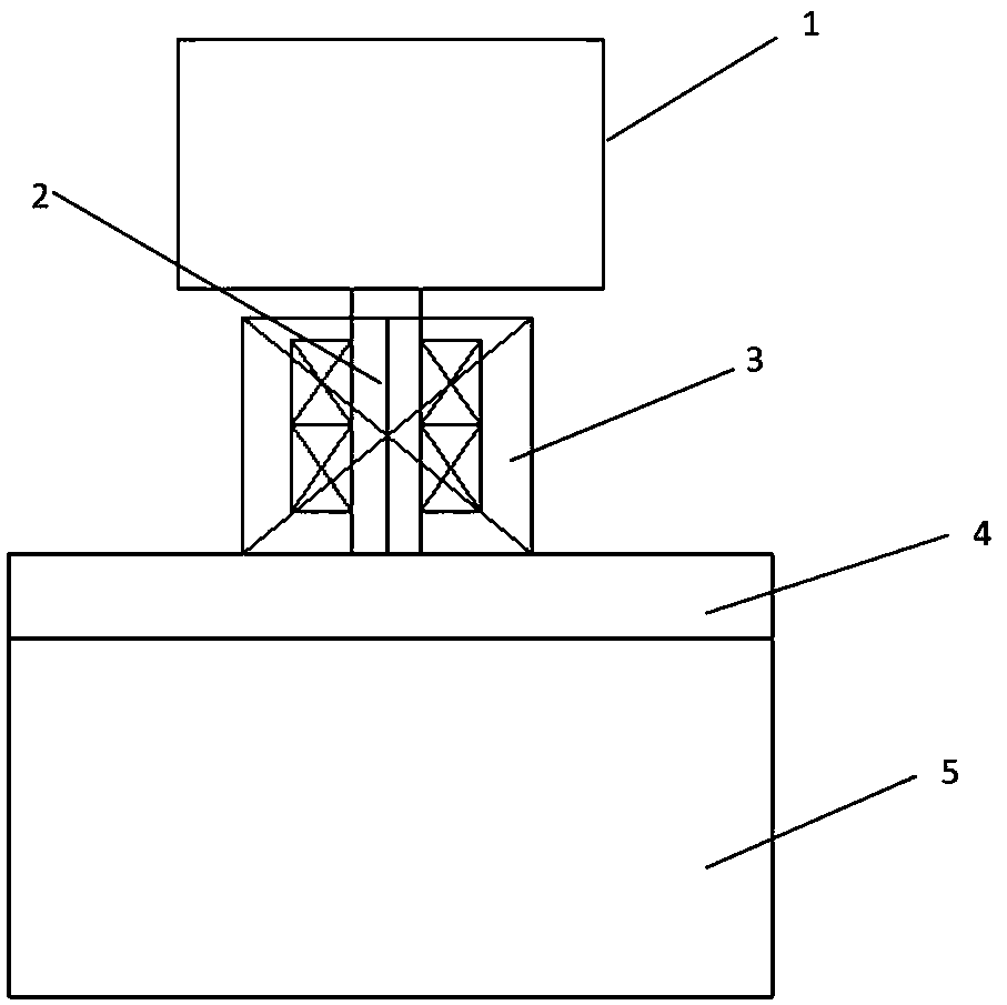
[0023] Embodiment one: see figure 1 As shown, an aluminum alloy low-pressure casting device includes a cavity 1, a liquid riser 2, an electromagnetic stirrer 3, a furnace cover 4, and a crucible furnace 5 from top to bottom; the furnace cover 4 is used to seal the crucible furnace 5, The upper part of the liquid riser 2 cooperates with the mold cavity 1 , and the electromagnetic stirrer 3 is placed around the liquid riser 2 and electromagnetically stirs the molten metal flowing through the liquid riser 2 .

[0024] Wherein, the electromagnetic stirrer 3 can adopt various forms in the prior art, and its function is to generate an alternating magnetic field after the power is turned on to stir the molten metal in the liquid riser.

[0025] When pouring, first keep the temperature of the metal melt near the liquidus line. After the pouring starts, the molten metal flows upward from the crucible furnace 5 along the riser 2. The molten metal in the casting is stirred rapidly to ac...


PUM


Abstract

The invention discloses a low-pressure filling method and device using electromagnetic stirring technology. The device includes a crucible furnace and a riser tube. The crucible furnace is provided with a furnace cover, so that the inside of the crucible furnace forms a sealed cavity. The top of the sealed cavity is communicated to the bottom of the cavity to be filled through a riser tube. An electromagnetic stirrer is provided beside the riser tube, and the crucible furnace has a pressurized gas inlet. Pressure is applied to metal melt in the crucible furnace to make the metal melt rise through the riser. Under the filling pressure, the metal melt enters the cavity smoothly until the entire cavity is completely filled. The temperature of the metal melt passing through the riser is 30 to60% of the liquidus temperature of the metal or alloy plus the width of its solidification temperature interval; As the metal melt flows through the riser, the metal melt is electromagnetically stirred. The device disclosed in the invention uses electromagnetic stirring to break up the generated dendrites, new crystal nuclei are added, the grain structure is refined, the pouring temperature is lowered, the mechanical properties of the casting can be improved, air intake and shrinkage of the casting can be reduced, and the casting quality and metal utilization rate can be improved.

Description

technical field [0001] The invention relates to a low-pressure casting method, in particular to a mold filling method in low-pressure casting, especially a low-pressure mold filling method using electromagnetic stirring technology. Background technique [0002] Low-pressure casting is a method of making liquid metal fill the cavity from bottom to top along the riser pipe under the action of pressure to overcome gravity and other resistances, and obtain castings under pressure. The pressure used is low, and the pressure in the filling stage is generally 20-70 kPa, so it is called low-pressure casting. Low-pressure casting has the advantages of easy adjustment of pouring pressure and speed, stable mold filling, easy realization of sequential solidification, and high utilization of molten metal. [0003] The process of low-pressure casting includes the liquid lifting stage, the filling stage and the solidification and crystallization stage. In the filling stage, the fluidity ...

Claims


Application Information

Patent Timeline
IPC IPC(8): B22D18/04B22D1/00
CPCB22D1/007B22D18/04
Inventor 杨林龙
Owner SUZHOU MINGZHI TECH
Why Eureka
Try Eureka