Eureka AIR delivers breakthrough ideas for toughest innovation challenges, trusted by R&D personnel around the world.

High-property T iron punching device for loudspeaker

A punching equipment, high-performance technology, applied in the direction of drilling/drilling equipment, metal processing equipment, boring/drilling, etc., can solve the problems of low drilling efficiency, affecting output, reducing revenue, etc., to achieve drilling The effect of maximizing the space, increasing the drilling speed and improving the drilling efficiency

Active Publication Date: 2020-02-25
嘉兴尚乐机电股份有限公司
View PDF4 Cites 7 Cited by
  • Summary
  • Abstract
  • Description
  • Claims
  • Application Information

AI Technical Summary

Problems solved by technology

[0003] The existing T-iron drilling equipment is relatively lacking, and it is generally a semi-automatic small machine, which does not have the integrated function of simultaneous loading, processing and unloading, and the drilling method is mostly the T-iron horizontal delivery to the bottom of the drill bit, The speed of punching is slow, and the space for punching is not maximized, so the efficiency of punching is low, which affects the output, and the punching is usually in a straight-forward way, without a buffer mechanism, which is easy to damage the T Iron, which in turn affects product quality and reduces revenue

Method used


Image

  • High-property T iron punching device for loudspeaker
  • High-property T iron punching device for loudspeaker
  • High-property T iron punching device for loudspeaker

Examples


Embodiment Construction

[0028] In order to make the technical means, creative features, goals and effects achieved by the present invention easy to understand, the present invention will be further elaborated below in conjunction with illustrations and specific embodiments.

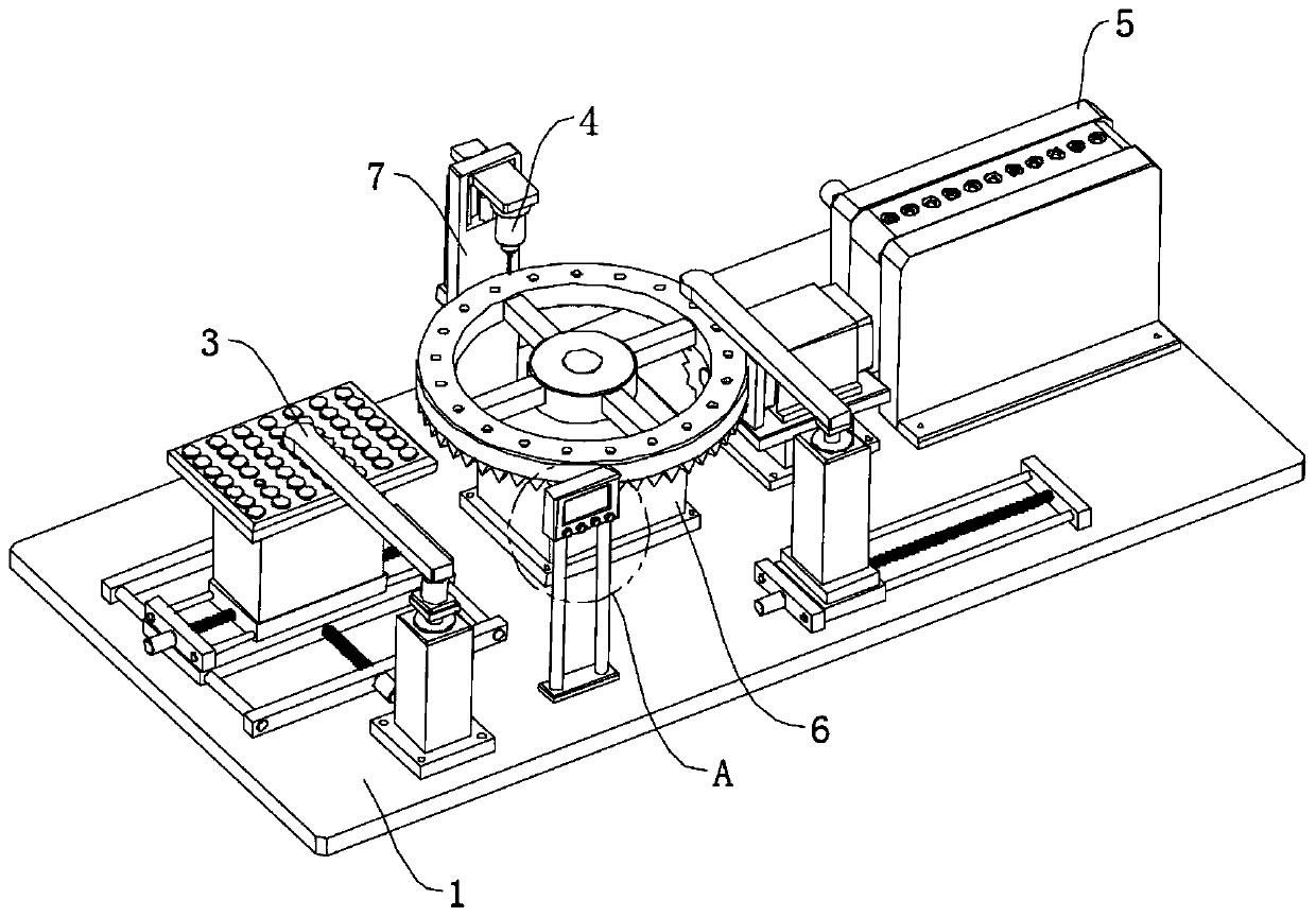
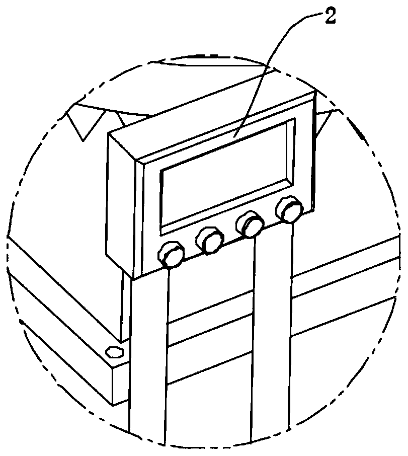
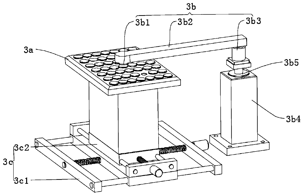
[0029] refer to Figure 1 to Figure 8 The shown high-performance T-iron drilling equipment for loudspeakers includes a base 1, and also includes a controller 2, a feeding mechanism 3, a punching mechanism 4 and a feeding mechanism 5. The controller 2 is arranged on the base, and the The feeding mechanism 3 is arranged on the top end of the base 1 to feed T iron. The feeding mechanism 3 includes a placement platform 3a and a first adsorption assembly 3b, and the placement platform 3a is arranged on the top of the base 1 through a sliding assembly 3c. The first adsorption assembly 3b is arranged on the side of the placement table 3a, and the punching mechanism 4 is arranged between the feeding mechanism 3 and the unloading mechani...


PUM


Abstract

The invention relates to the technical field of T iron machining, and provides a high-property T iron punching device for a loudspeaker. The high-property T iron punching device comprises a base and further comprises a controller, a loading mechanism, a punching mechanism and a discharging mechanism. The loading mechanism comprises a placing table and a first absorbing assembly, the punching mechanism comprises a rotating disc, a driving assembly and a drilling assembly, the discharging mechanism is arranged on the other end of the top of the base in a through manner to discharge drilled T iron, the discharging mechanism comprises a conveying belt and a second absorbing assembly, the second absorbing assembly is slidingly arranged beside the rotating disc, the conveying belt is arranged onthe end, away from the top of the placing table, of the base, and the first absorbing assembly, the driving assembly and the second absorbing assembly are electrically connected with the controller.According to the loudspeaker high-property T iron punching device, the T iron punching operation space is maximized, the punching efficiency is improved, the yield is increased, meanwhile, it can be effectively ensured that the T iron is not damaged by too large drilling strength, and the T iron quality is ensured.

Description

technical field [0001] The invention relates to the technical field of T-iron processing, in particular to a high-performance T-iron punching device for loudspeakers. Background technique [0002] T iron, also called electrical iron, is made of pure iron. It is an integral part of the sound unit. In the sound unit, the main function of the T iron is to conduct magnetism under the condition of electrification, but it has no residual magnetism. When the speaker is powered off, the magnetic field disappears, and its magnetism also disappears immediately. Therefore, the purity of t iron will directly affect the working efficiency of the sound unit and some important parameters of nonlinear distortion. Related to the t iron is the splint, both of which are components of the sound unit. The thickness of the splint directly affects the stroke of the sound unit. For a long-stroke unit, the T iron and the splint are very thick, and they can basically make the entire stroke of the...

Claims


Application Information

Patent Timeline
Patent Type & Authority Applications(China)
IPC IPC(8): B23B41/00B23B49/00B23Q7/04B23Q7/02B23Q7/10
CPCB23B41/00B23B49/00B23Q7/02B23Q7/04B23Q7/10
Inventor 将文明李永涛
Owner 嘉兴尚乐机电股份有限公司
Why Eureka
Eureka Blog
Learn More