A new energy vehicle drive motor enameled wire paint remover remover machine

A new energy vehicle and drive motor technology, applied in the direction of circuits, electrical components, circuit/collector components, etc., can solve the problems of stabbing hands, low removal efficiency, and low safety, and achieve faster drying speed and removal efficiency High and safe effect

Active Publication Date: 2021-02-19
威海云之卫智能科技有限公司
View PDF9 Cites 0 Cited by
  • Summary
  • Abstract
  • Description
  • Claims
  • Application Information

AI Technical Summary

Problems solved by technology

[0005] In order to overcome the shortcomings that people can only remove a small amount of paint remover at one time, resulting in low removal efficiency, and people will stab their hands if they are not careful, and the shortcomings of low safety, the technical problem of the present invention is: to provide a paint remover High-efficiency, high-safety new energy vehicle drive motor enameled wire depainting machine for paint remover

Method used


Image

  • A new energy vehicle drive motor enameled wire paint remover remover machine
  • A new energy vehicle drive motor enameled wire paint remover remover machine
  • A new energy vehicle drive motor enameled wire paint remover remover machine

Examples


Embodiment approach 1

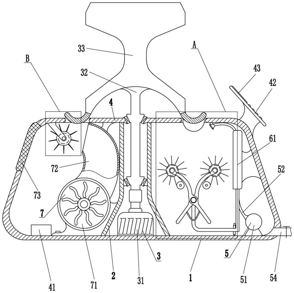
[0025] as attached figure 1 with Figure 5 As shown, a new energy vehicle drive motor enameled wire paint remover remover includes a box 1, a partition 2, a rotating mechanism 3, a horizontal plate 4 and a flushing mechanism 5, and the middle part of the box 1 is connected with two A partition 2, a rotating mechanism 3 is provided between the two partitions 2, the rotating mechanism 3 is used to drive the enameled wire to rotate, the top of the two partitions 2 is connected with a horizontal plate 4, and the right side of the inner bottom of the box body 1 is equipped with a flushing mechanism 5. The flushing mechanism 5 is used to flush the enameled wire.

[0026] as attached figure 1 , Image 6 with Figure 7 Shown, also comprise control module, LCD display screen 43, setting key, plus one key, minus one key and confirmation key, LCD display screen 43, setting key, plus one key, minus one key and confirmation key are all connected with control module through electrical ...

Embodiment approach 2

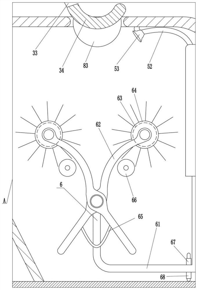
[0033] On the basis of Embodiment 1, as attached figure 1 with figure 2 As shown, a cleaning mechanism 6 is also included, and the cleaning mechanism 6 includes an electric push rod 61, a hinged frame 62, a first driving motor 63, a first roller brush 64, a shrapnel 65, a roller 66, a first travel switch 67 and a second Stroke switch 68, an electric push rod 61 is installed on the right side of the box body 1, and the box body 1 is connected with the electric push rod 61 through a bolt connection mode. The electric push rod 61 is rotatably connected with two hinged frames 62. The first drive motor 63 is installed on the top of the frame 62, and the first roller brush 64 is rotatably connected to the top of the two hinged frames 62, and the rear end of the first roller brush 64 is connected with the output shaft of the first drive motor 63. A shrapnel 65 is connected between the frames 62, and two rollers 66 are mounted on the rear right side of the box body 1 in a rotating m...


PUM


Abstract

The invention relates to a paint stripper remover, in particular to a paint remover remover for new energy vehicle drive motor enameled wires. The technical problem of the present invention is how to provide a paint remover remover with high removal efficiency and high safety for enameled wires of drive motors of new energy vehicles. The paint remover remover includes a box body, a partition, a rotating mechanism, etc.; two partitions are connected in the middle of the bottom of the box, and a rotating mechanism is arranged between the two partitions. The rotating mechanism is used to drive the enameled wire to rotate. The invention can control the flushing mechanism through the control module to remove the paint stripper on the enameled wire. Since the motor stator is rotating, the paint remover on multiple enameled wires can be removed, the removal efficiency is high, and the paint stripper can be automatically removed. The lacquer is removed, so that the copper wire can be avoided from stabbing people's hands, and the safety is high.

Description

technical field [0001] The invention relates to a paint stripper remover, in particular to a paint remover remover for new energy vehicle drive motor enameled wires. Background technique [0002] Enameled wire is a main variety of winding wire, which is composed of conductor and insulating layer. When manufacturing mechanical parts such as motor stators, in order to facilitate line connection, it is necessary to remove the paint from the enameled wire. After the paint removal is completed, in order not to affect the use, it is necessary to Remove the paint stripper remaining on the enameled wire. [0003] At present, people generally dip a rag in water, and then remove the paint remover on the enameled wire, but more enameled wires are needed on the motor stator, and people can only remove a small amount of paint remover at one time, resulting in low removal efficiency , and the copper wire in the enameled wire is relatively sharp, people will stab their hands a little care...

Claims


Application Information

Patent Timeline
Patent Type & Authority Patents(China)
IPC IPC(8): H01R43/28
CPCH01R43/28
Inventor 廖优优
Owner 威海云之卫智能科技有限公司
Why Eureka
Try Eureka