Friction welding device capable of removing outer flashings through forward pushing type turning and use method thereof

A technology of friction welding and pushing device, which is applied in the field of friction welding, can solve the problems of rapid tool wear, narrow and difficult burrs in friction welding, etc., and achieves the effects of flexible use, high positioning accuracy and improved efficiency.

Pending Publication Date: 2020-02-28
SHANXI SHENZHOU AEROSPACE SCI & TECH CO LTD
View PDF0 Cites 3 Cited by
  • Summary
  • Abstract
  • Description
  • Claims
  • Application Information

AI Technical Summary

Problems solved by technology

The existing method of removing the welding flash of friction welding can only be removed by taking it to other machining equipment after welding. On the one hand, in addition to configuring a lathe or a punching The content of carbon or alloy elements is high, and it has a certain quenching tendency, and the flash of friction welding is very narrow, and it is located around the weldment. The cooling rate after welding is very fast, and because the flash metal has undergone severe deformation During the process, the hardness and strength of the flash after cooling are very high, and the wear of the cutting tool is very fast. Both manual and mechanical methods have certain difficulties

Method used


Image

  • Friction welding device capable of removing outer flashings through forward pushing type turning and use method thereof
  • Friction welding device capable of removing outer flashings through forward pushing type turning and use method thereof
  • Friction welding device capable of removing outer flashings through forward pushing type turning and use method thereof

Examples


Embodiment Construction

[0031] The following will clearly and completely describe the technical solutions in the embodiments of the present invention with reference to the accompanying drawings in the embodiments of the present invention. Obviously, the described embodiments are only some, not all, embodiments of the present invention. Based on the embodiments of the present invention, all other embodiments obtained by persons of ordinary skill in the art without making creative efforts belong to the protection scope of the present invention.

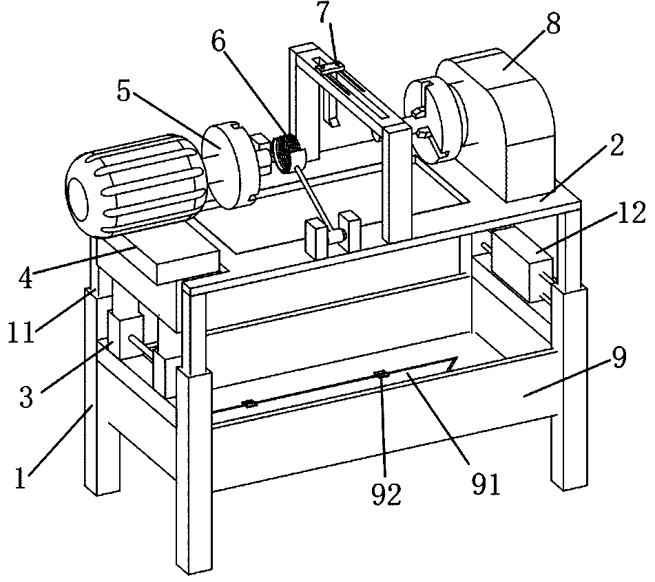
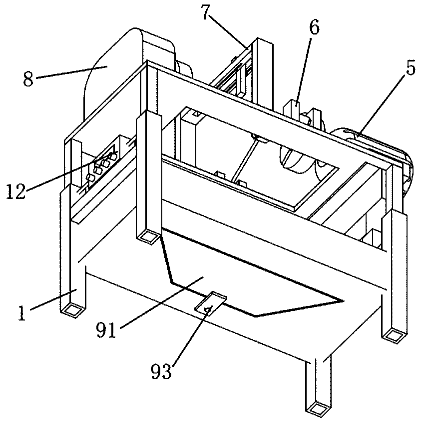
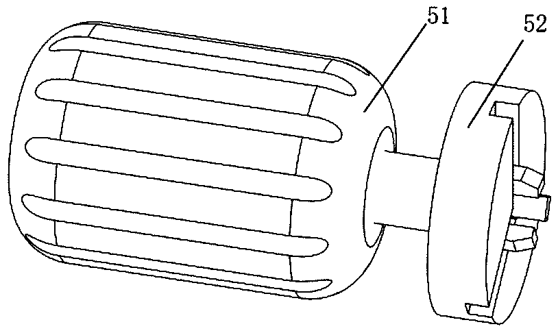
[0032] see Figure 1 to Figure 6 , a friction welding device for forward-push turning to remove external flash provided by the present invention, comprising two H-shaped support frames 1 and a storage plate 2, the two H-shaped support frames are arranged side by side, and the interior adopts a hollow structure, and the support frame A hydraulic lifting frame 11 is installed inside, and the storage plate 2 is fixed on the hydraulic support frame. The height of ...


PUM


Abstract

The invention relates to the frication welding technology field, in particular to a friction welding device capable of removing outer flashings through forward pushing type turning and a use method thereof. The friction welding device comprises two H-shaped support frames and an object placing plate, wherein the object placing plate is fixed above the H-shaped support frames, a hydraulic lifting pillar is fixed on a cross beam on the H-shaped support frame on one side, a lifting board is fixed at the top of the hydraulic lifting pillar, a notch adaptive to the lifting board is formed in the object placing plate and used for enabling the lifting board to pass, a friction device is fixed on the lifting board, the friction device comprises a friction welding motor and a three-jaw workpiece fixer I, the three-jaw workpiece fixer I is fixed on a motor shaft of the friction welding motor, an induction heating device, a turning device and a pushing device are further sequentially fixed on theobject placing plate and in the direction of the motor shaft of the friction welding motor, the pushing device comprises a pushing hydraulic pump and a three-jaw workpiece fixer II installed on the pushing hydraulic pump, and the three-jaw workpiece fixer I and the three-jaw workpiece fixer II are oppositely arranged.

Description

technical field [0001] The invention relates to the technical field of friction welding, in particular to a friction welding device and a use method for forward-push turning to remove outer flash. Background technique [0002] Since friction welding was invented in 1991, this technology has appeared in many fields at home and abroad. During friction welding, the metal of the weldment near the weld is in a high temperature plastic state. Under high stress, the metal in the plastic state is continuously extruded from the welding surface, forming an annular welding flash around the weld seam. In most cases, the welding flash needs to be removed due to the use requirements of the weldment or the requirements of the appearance shape. The existing method of removing the welding flash of friction welding can only be removed by taking it to other machining equipment after welding. On the one hand, in addition to configuring a lathe or a punching The content of carbon or alloy ele...

Claims


Application Information

Patent Timeline
IPC IPC(8): B23P23/02B23K20/12
CPCB23P23/02B23K20/122
Inventor 杨兴山化宜文申晓杰王腾
Owner SHANXI SHENZHOU AEROSPACE SCI & TECH CO LTD
Why Eureka
Try Eureka