An optical fiber sensor transfer box with moisture-proof function

An optical fiber sensor and transfer box technology, which is applied in the direction of preventing rotten containers, containers, rigid containers, etc., can solve the problem that the optical fiber sensor is susceptible to external force and natural environment, and achieves the effect of increasing moisture resistance, avoiding air leakage, and increasing the protection effect. Effect

Active Publication Date: 2021-03-16
株洲菲斯罗克光电科技股份有限公司
View PDF4 Cites 1 Cited by
  • Summary
  • Abstract
  • Description
  • Claims
  • Application Information

AI Technical Summary

Problems solved by technology

[0004] Based on the technical problem that the optical fiber sensor transferred by the existing transfer box is easily affected by external force and natural environment during the transfer process of the optical fiber sensor, the present invention proposes a fiber optic sensor transfer box with moisture-proof function

Method used


Image

  • An optical fiber sensor transfer box with moisture-proof function
  • An optical fiber sensor transfer box with moisture-proof function
  • An optical fiber sensor transfer box with moisture-proof function

Examples


Embodiment 1

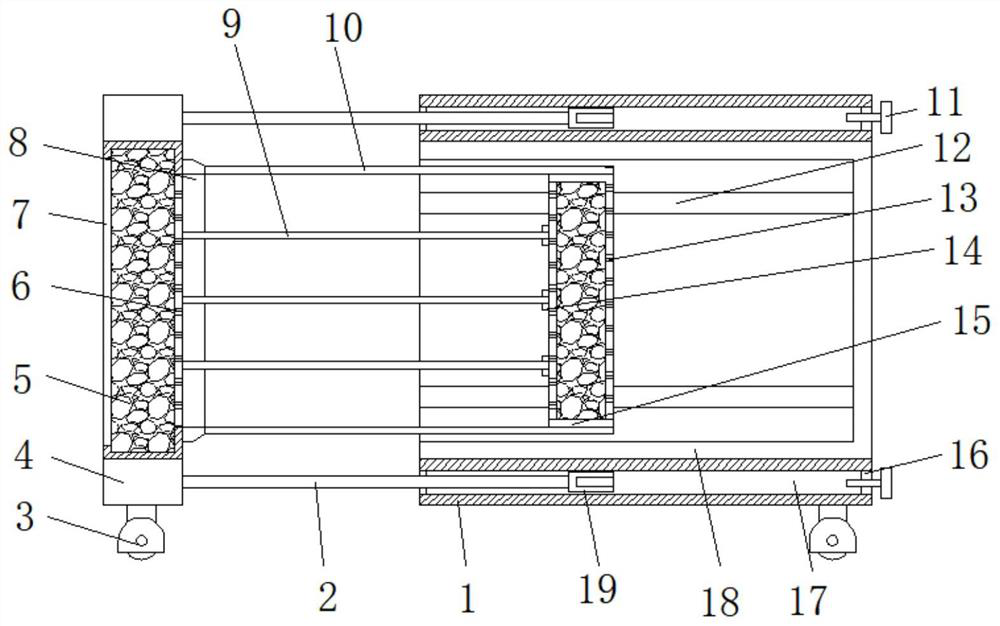
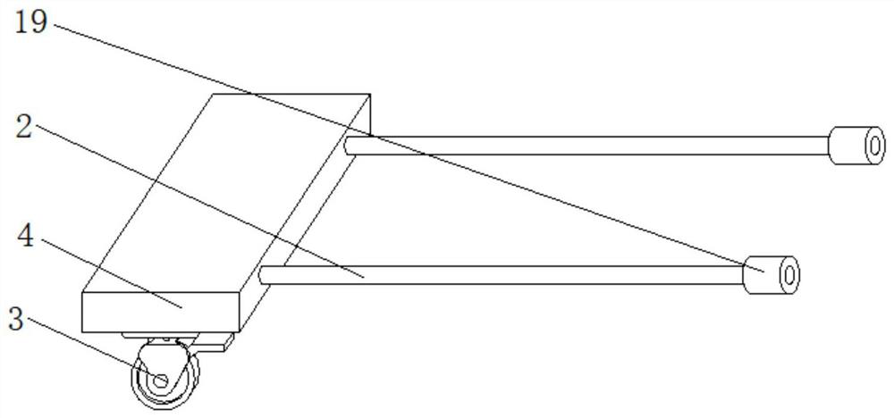
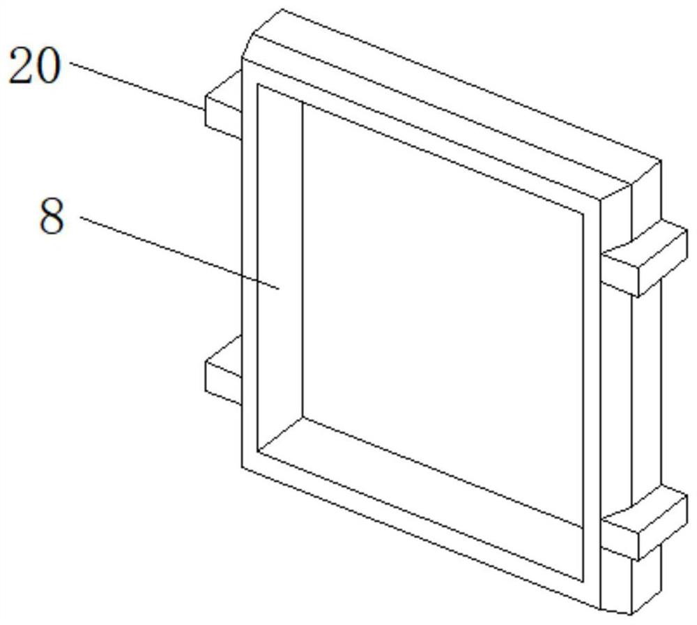
[0026] refer to Figure 1-4 , an optical fiber sensor transfer box with moisture-proof function, including a box body 18, the top and bottom of the box body 18 are equipped with a connecting plate 1, and the sides of the two connecting plates 1 are provided with two circular through holes 17, The limit slide bar 2 is slidably installed inside the circular through hole 17 , the auxiliary connecting plate 4 is installed between the ends of the two adjacent limit slide bars 2 , and the casing is installed between the two auxiliary connecting plates 4 7. The interior of the housing 7 is filled with silica gel discoloration desiccant 5. Two universal wheels 3 with foot brakes are installed at the bottom ends of the lower connecting plate 1 and the auxiliary connecting plate 4. The side of the housing 7 is welded with a seal. Frame 8, and two cargo boards 10 are welded on the side of the sealing frame 8, a reinforcement bracket 15 is installed between the two cargo boards 10, and tw...

Embodiment 2

[0033] refer to Figure 1-4 , an optical fiber sensor transfer box with moisture-proof function, further, the reinforcement bracket 15 is a box-type structure, and the interior of the reinforcement bracket 15 is filled with a desiccant bag, and both sides of the reinforcement bracket 15 are provided with a plurality of ventilation holes 13, Filling the desiccant bag inside the reinforcement bracket 15 can increase the moisture-proof effect of the transfer box. At the same time, the ventilation holes 13 on both sides are arranged, and the reinforcement bracket 15 is used to drive out the interior of the box body 18 when the cargo board 10 and the auxiliary cargo board 9 are inserted. air, and dehumidify the air to further increase the protection effect of the fiber optic sensor;

[0034] The side of the reinforcement bracket 15 is welded with a plurality of card seats 14, and the end of the sub-cargo board 9 is inserted into the inside of the card seat 14, and the end of the su...


PUM


Abstract

The invention belongs to the technical field of optical fiber sensor transfer, and particularly relates to an optical fiber sensor transfer box with a dampproof function. The problems that according to existing transfer boxes, in the transfer process of optical fiber sensors, the transferred optical fiber sensors are prone to being affected by external force and the natural environment are solved.According to the scheme, the optical fiber sensor transfer box comprises a box body; connecting plates are installed at the top and the bottom of the box body; and the side face of each connecting plate is provided with two round through holes. According to the transfer box, a shell body and the box body are tensioned through a fastening mechanism, a barrel body and a limiting sliding rod, the internal space of the box body is sealed, the dry environment inside the transfer box is maintained through a silica-gel discolored desiccant inside the shell body, the service life of the optical fibersensor is prevented from being affected by damp, the dampproof effect of the transfer box is improved, meanwhile, the optical fiber sensors are stacked between carrying plates and auxiliary carryingplates and can be drawn out when needed, feeding and discharging operation of cargoes in the transfer box is facilitated, and using is easy and convenient.

Description

technical field [0001] The invention relates to the technical field of optical fiber sensor transport, in particular to an optical fiber sensor transport box with moisture-proof function. Background technique [0002] The optical fiber sensor is a sensor that converts the state of the measured object into a measurable optical signal. The working principle of the optical fiber sensor is to send the light beam incident from the light source into the modulator through the optical fiber, and the interaction between the measured parameters in the modulator and the outside world. It can change the optical properties of light such as light intensity, wavelength, frequency, phase, polarization state, etc., and become a modulated optical signal, which is then sent to the optoelectronic device through the optical fiber, and the measured parameters are obtained after the demodulator. It is developing in the direction of being sensitive, precise, adaptable, compact and intelligent. In ...

Claims


Application Information

Patent Timeline
Patent Type & Authority Patents(China)
IPC IPC(8): B65D25/02B65D25/24B65D81/26B65D25/00B65D53/00B65D85/86
CPCB65D25/005B65D25/02B65D25/24B65D53/00B65D81/26B65D81/266B65D2585/86
Inventor 王已熏易军刘小勇邵振华冯毅
Owner 株洲菲斯罗克光电科技股份有限公司
Why Eureka
Try Eureka