Automatic processing device of thermal power plant mortar

An automatic processing and thermal power plant technology, applied in the field of thermal power plants, can solve the problems of many operating points, large water consumption, poor operation, etc., to ensure the filtering effect and reduce the effect of shaking

Inactive Publication Date: 2020-02-28
西安沃唯隆控制系统有限公司
View PDF2 Cites 0 Cited by
  • Summary
  • Abstract
  • Description
  • Claims
  • Application Information

AI Technical Summary

Problems solved by technology

[0003] According to the Chinese patent No. CN 205974097 U, a thermal power plant desulfurization waste water circulation treatment device can solve the problem that the existing desulfurization waste water treatment devices have many operating points, complex control, and generally have poor operation of desulfurization waste water devices, but For the poor ash removal effect of the ash particles in the boiler and dust collector, according to the Chinese patent No. CN 206174035U, a thermal power plant water circulation system can solve the problem of large water resource consumption in the thermal power plant, and can process the processed water in the thermal power plant. A large amount of waste water is recycled to the slag extractor, which realizes the recycling of water in thermal power plants and reduces the waste of water resources, but the effect on waste water treatment is not good, so a device with good treatment effect and effective treatment of mortar is needed

Method used


Image

  • Automatic processing device of thermal power plant mortar
  • Automatic processing device of thermal power plant mortar

Examples


Embodiment 1

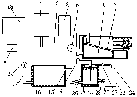
[0023] Example 1, please refer to Figure 1-2 , according to an embodiment of the present invention, an automatic processing device for ash in a thermal power plant includes a boiler 1, a dust collector 2 is connected to one side of the boiler 1, and both the boiler 1 and the dust collector 2 are connected to the ash flushing water pipe 3 , one end of the gray flushing water pipe 3 is connected to the water supply device 4, the other end of the gray flushing water pipe 3 is located at the top of the filter box one 5, the gray flushing water pipe 3 is connected with a mortar pump 6, and the filter box one The inside of 5 is fixedly connected with a filter screen 7. It should be noted that the filter screen 7 is obliquely connected with the filter box-5, and the port of the gray water pipe 3 is located on the higher side of the filter screen 7. The filter box-5 One side of one side is provided with baffle plate 8, and baffle plate 8 is positioned at the lower side of filter scre...

Embodiment 2

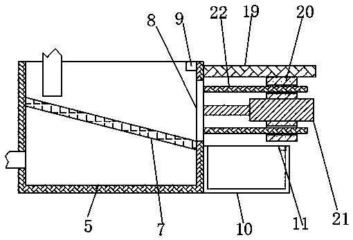
[0026] Example 2, please refer to figure 2 , the moving mechanism includes a support plate 19, a support frame 20 and a hydraulic telescopic rod 21, the top of one side of the filter box 5 close to the baffle plate 8 is fixedly connected with a support plate 19, and the bottom of the support plate 19 is fixed A support frame 20 is connected, and a hydraulic telescopic rod 21 is fixedly connected to the support frame 20 , and the movable end of the hydraulic telescopic rod 21 is fixedly connected to the baffle plate 8 .

Embodiment 3

[0027] Embodiment three, please refer to figure 2 , the side of the baffle plate 8 close to the hydraulic telescopic rod 21 is fixedly connected with a guide rod 22, the guide rod 22 is respectively located above and below the hydraulic telescopic rod 21, and the guide rod 22 is far away from the baffle. One end of the board 8 passes through the support frame 20 and extends to the other side of the support frame 20 , and the support frame 20 is provided with a corresponding hole for the guide rod 22 to pass through.


PUM


Abstract

The invention discloses an automatic processing device of thermal power plant mortar. The automatic processing device comprises a boiler. One side of the boiler is connected to a deduster. The boilerand the deduster are both connected to an ash removing water pipe. One end of the ash removing water pipe is connected to a water supply device. The other end of the ash removing water pipe is arranged on the top of a filter box (A). A filter screen is fixedly connected to the interior of the filter box (A). One side of the filter box (A) is provided with a baffle plate. The baffle plate is connected to a moving mechanism. One side, which is far away from the baffle plate, of the filter box (A) is connected to a filter box (B) through a pipeline (A). A micro-porous film is connected to the interior of the filter box (B). The top of the filter box (B) is connected to a cleaning mechanism. One side of the filter box (B) is connected to a clean water tank through a pipeline (B). The clean water tank is connected to the ash removing water pipe through a return pipe. One side of the boiler is provided with a controller. The automatic processing device has the advantages that the wastewatercan be reused, and at the same time, the filter screen and micro-porous film can be cleaned automatically.

Description

technical field [0001] The invention relates to the technical field of thermal power plants, in particular to an automatic processing device for mortar in thermal power plants. Background technique [0002] A thermal power plant is a factory that uses coal, oil, and natural gas as fuel to produce electric energy. Its basic production process is: the fuel is burned in a boiler to heat water to make steam, and the chemical energy of the fuel is converted into heat energy. The steam pressure drives the steam turbine to rotate, and the heat energy It is converted into mechanical energy, and then the steam turbine drives the generator to rotate to convert the mechanical energy into electrical energy. When the boiler is burning, there will be a large amount of ash particles and other substances in the boiler and dust collector. If it is not removed, it will affect the heat transfer efficiency. In order to reduce Human labor, now using hydraulic power to remove ash, but the waste w...

Claims


Application Information

Patent Timeline
Patent Type & Authority Applications(China)
IPC IPC(8): C02F9/02
CPCC02F1/001C02F1/444C02F2303/14
Inventor 吕鑫
Owner 西安沃唯隆控制系统有限公司
Why Eureka
Try Eureka