Gasification furnace chilling chamber containing flow-guiding cylinder and application method thereof

A technology of gasifier and chilling chamber, which is applied in gasification process, granular/powder fuel gasification, manufacture of combustible gas, etc., to achieve the effect of increasing contact area, reducing bubble size and uniform distribution

Pending Publication Date: 2020-02-28
INST OF PROCESS ENG CHINESE ACAD OF SCI
View PDF3 Cites 3 Cited by
  • Summary
  • Abstract
  • Description
  • Claims
  • Application Information

AI Technical Summary

Problems solved by technology

[0007] Aiming at the deficiencies in the prior art, the purpose of the present invention is to provide a gasification furnace quenching chamber containing a draft tube and its use method. The present invention forms a liquid circulation by setting the draft tube to prevent the deposition of fine coal ash particles, Effectively solve the clogging problem caused by fine particles; by installing a gas distribution device, small bubbles can be effectively formed, the phase boundary area of ​​the bubbles is increased, and the effect of water bath humidification, dust removal, ash removal and cooling is greatly improved, thereby reducing the excessive entrainment of syngas Coal ash enters the next section; in addition, the formation of small air bubbles is beneficial to prevent engineering problems such as fluctuations caused by super large air bubbles leaving the liquid surface and liquid level alarm trips caused

Method used


Image

  • Gasification furnace chilling chamber containing flow-guiding cylinder and application method thereof
  • Gasification furnace chilling chamber containing flow-guiding cylinder and application method thereof

Examples


Embodiment 1

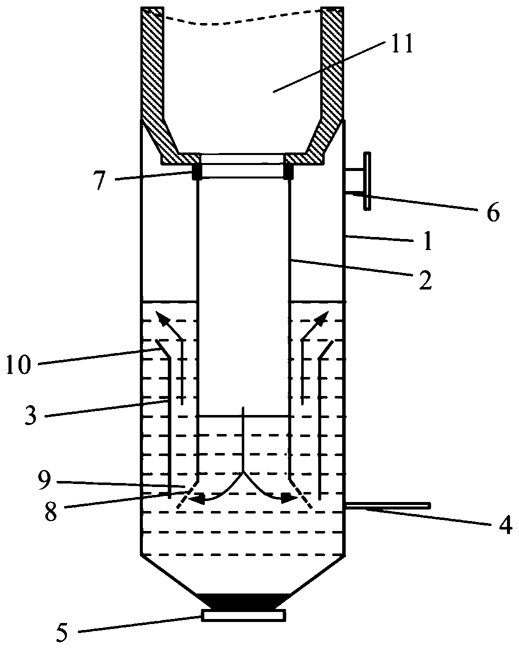
[0055] This embodiment provides a figure 1 The quenching chamber of the gasification furnace shown includes a shell 1 , a downcomer 2 is arranged inside the shell 1 , and a coaxial guide tube 3 is set on the outside of the downcomer 2 . An annular gap is formed between the guide tube 3 and the downcomer 2 . One end of the downcomer 2 is connected to the gasifier 11, and the other end is provided with a gas distribution device. The gas distribution device is a conical section 8 connected to the outer edge of the downcomer 2. The air hole 9 is set on the conical section 8, and the air hole 9 runs along the conical section. 8 is arranged in the circumferential direction, and the shape of the air hole 9 is circular. The synthesis gas produced by the gasifier 11 enters the downcomer 2 and then passes through the pores 9 on the conical section 8 to be introduced into the annular gap, and the diameter of the conical section 8 gradually increases along the direction of the syngas.

...

Embodiment 2

[0061] This embodiment provides a method for using the quenching chamber of the gasifier described in Embodiment 1, and the method specifically includes the following steps:

[0062] (I) The synthesis gas and molten slag produced by the gasifier 11 enter the downcomer 2, and at the same time, quenching water is passed into the quenching ring 7, and the quenching water is sprayed out from the nozzle and descends along the inner wall of the downcomer 2 to form a liquid film;

[0063] (II) The synthesis gas passes through the downcomer 2 and is dispersed into small bubbles through the air holes 9 on the tapered section 8, and then enters the annulus, and the bubbles pass through the annulus and are discharged from the exhaust port 6;

[0064] (Ⅲ) The molten slag passed through the downcomer 2 settles and accumulates at the bottom of the quenching chamber of the gasifier, and is regularly discharged from the slag outlet 5 , and fine particles in the molten slag are discharged throu...

Embodiment 3

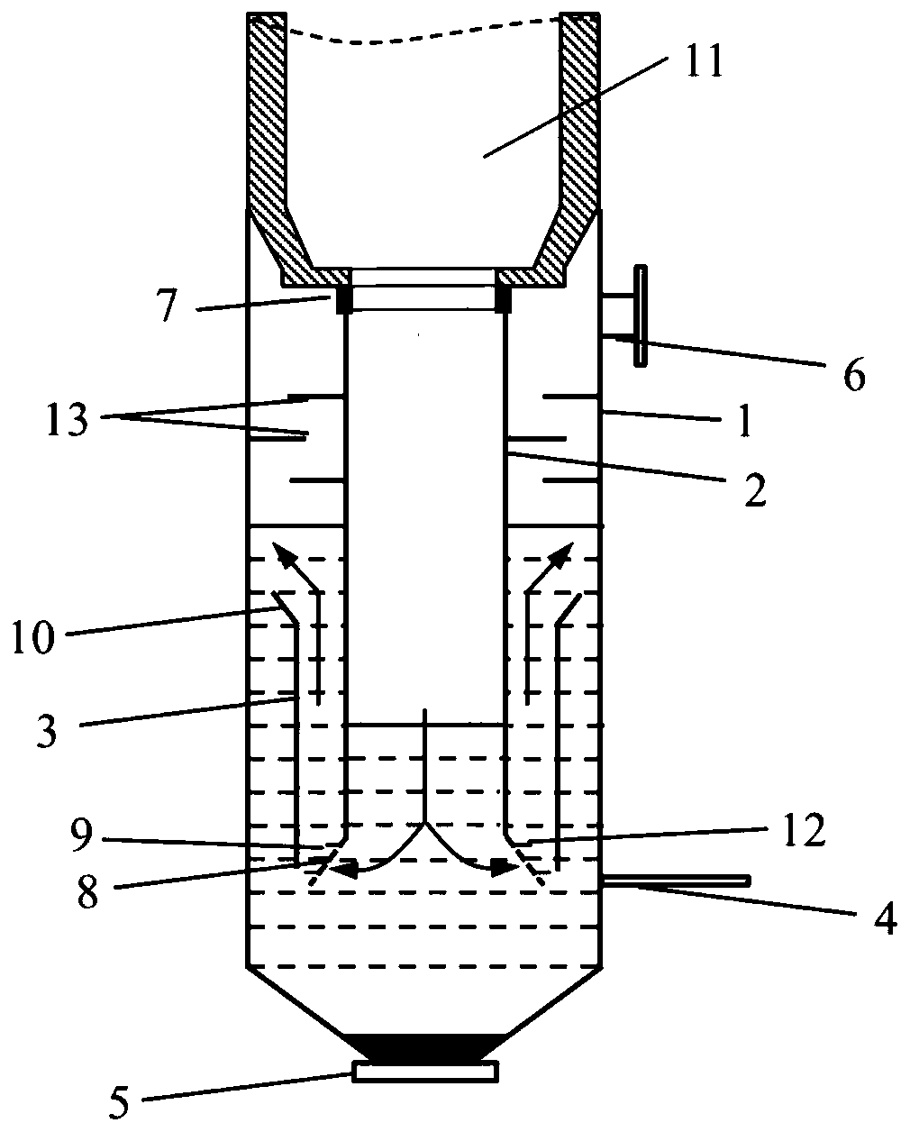
[0066] This embodiment provides a figure 2 The quenching chamber of the gasification furnace shown includes a casing 1, a downcomer 2 is arranged inside the casing 1, and a coaxial guide tube 3 is set on the outside of the downcomer 2, and a coaxial guide tube 3 is formed between the guide tube 3 and the downcomer 2. annulus. One end of the downcomer 2 is connected to the gasifier 11, and the other end is provided with a gas distribution device. The gas distribution device is a conical section 8 connected to the outer edge of the downcomer 2. The air hole 9 is set on the conical section 8, and the air hole 9 runs along the conical section. 8 is arranged in the circumferential direction, the shape of the air hole 9 is square, and the air hole 9 is provided with a deflector 12 . The synthesis gas produced by the gasifier 11 enters the downcomer 2 and then passes through the pores 9 on the conical section 8 to be introduced into the annular gap, and the diameter of the conical ...


PUM


Abstract

The invention provides a gasification furnace chilling chamber containing a flow-guiding cylinder and an application method thereof. The gasification furnace chilling chamber comprises a shell, wherein a downcomer is arranged in the shell; the outer side of the downcomer is sleeved by a coaxial flow-guiding cylinder; an annular gap is formed between the flow-guiding cylinder and the downcomer; oneend of the downcomer is connected with a gasification furnace; the other end of the downcomer is provided with a gas distribution device which is a conical section in butt joint with the outer edge of the downcomer; and the conical section is provided with gas holes. According to the invention, liquid circulation is formed through arrangement of the flow-guiding cylinder, so deposition of fine coal ash particles is prevented, and the problem of blockage caused by fine particles is effectively solved; meanwhile, through arrangement of the gas distribution device, small bubbles can be effectively formed; the phase boundary area of the bubbles is increased; the humidifying, dust-removing, ash-removing and cooling effects of a water bath are greatly improved; thus, the situation that synthesis gas carries excessive coal ash to enter a next working section is reduced.

Description

technical field [0001] The invention belongs to the technical field of coal gasification equipment, and relates to a gasifier quenching chamber and a method of using the same, in particular to a gasifier quenching chamber containing a guide tube and a method of using the same. Background technique [0002] Coal gasification reaction and separation system is one of the core devices of coal chemical industry, and people pay more and more attention to the clean coal gasification technology to achieve high efficiency, low energy consumption and low pollution. High-pressure, large-capacity entrained-bed gasification technology is one of the most advanced coal gasification technologies in the world, and is widely used in the coal chemical industry. Modern entrained-bed gasification technology mainly includes coal-water slurry gasification and pulverized coal gasification technology, which has the advantages of less environmental pollution and high degree of automation. In the ent...

Claims


Application Information

Patent Timeline
Patent Type & Authority Applications(China)
IPC IPC(8): C10J3/84C10J3/48C10J3/72
CPCC10J3/48C10J3/72C10J3/84C10J2300/1603C10J2300/1615
Inventor 杨宁管小平
Owner INST OF PROCESS ENG CHINESE ACAD OF SCI
Why Eureka
Try Eureka