Laterally-arranged micro-interface enhanced reaction device and method for hydrogenation reactions of residual oil
A technology for residual oil hydrogenation and reaction device, applied in chemical instruments and methods, hydrocarbon oil cracking, petroleum industry, etc., can solve the problems of high safety risk, high investment, high material consumption, etc., and achieve low process severity and production safety. The effect of high performance and low cost per ton of product
- Summary
- Abstract
- Description
- Claims
- Application Information
AI Technical Summary
Problems solved by technology
Method used
Image
Examples
Embodiment 1
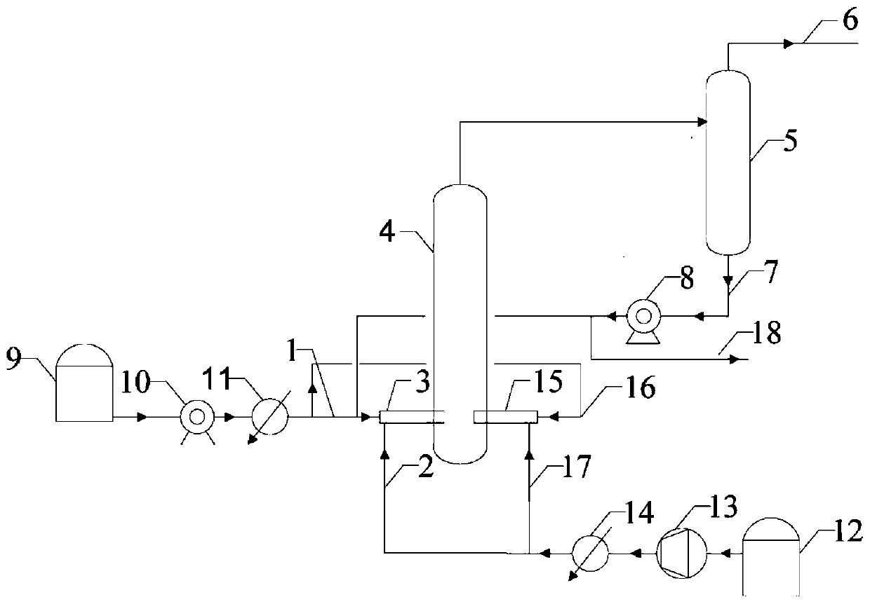
[0037] This embodiment specifies the device structure of the present invention, as figure 1 The shown side-mounted micro-interface strengthening reaction device for residual oil hydrogenation reaction includes:
[0038] Bubble reactor 4, the top is provided with the second outlet;
[0039] The air intake device includes a hydrogen buffer tank 12, a compressor 13 and a first preheater 14 connected in sequence, for raw gas delivery;
[0040] The liquid inlet device includes a residual oil raw material tank 9, a feed pump 10 and a second preheater 11 connected in sequence, for raw material liquid transportation;
[0041] At least one bubble breaker is arranged laterally at the lower part of the bubble reactor 4, and the bubble breaker is provided with a gas phase inlet, a liquid phase inlet and a first discharge port, and the first discharge port is connected to the bubble reactor. Reactor; the gas phase inlet is connected to the first preheater 14 of the inlet device, and the ...
Embodiment 2
[0049] This embodiment takes the hydrogenation ring-opening reaction of residual oil as an example to specifically illustrate an implementation of the method of the present invention.
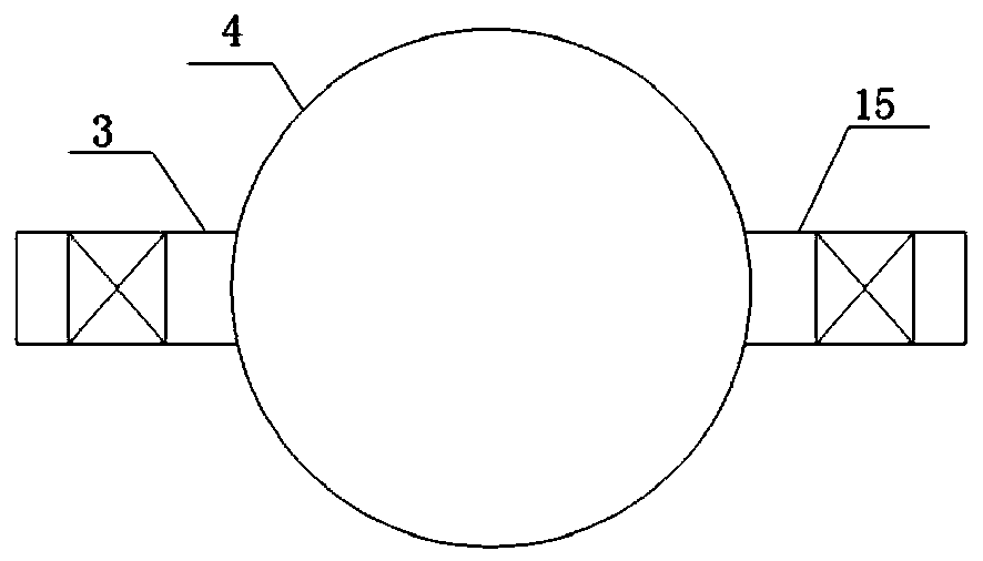
[0050] The residual oil raw material is extracted from the residual oil raw material tank 9, mixed with the catalyst through the feed pump 10, and then passed through the second preheater 11, and then passes through the liquid phase inlet 1 of the gas-liquid linkage bubble breaker and enters the In the gas-liquid linkage type bubble breaker 3 on the shell side of the bubble reactor 4, the other way enters the pneumatic bubble breaker 15 installed on the shell side of the bubble reactor 4 through the liquid phase inlet 16 of the pneumatic bubble breaker. middle. At the same time, the hydrogen raw material is extracted from the hydrogen buffer tank 12, passes through the compressor 13 and then the first preheater 14, and then passes through the gas phase inlet 2 of the gas-liquid linkage bubble b...
Embodiment 3
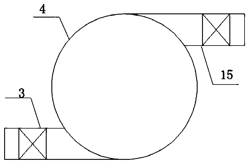
[0055] The difference between this embodiment and embodiment 2 is that the gas-liquid linkage type bubble breaker 3 and the pneumatic type bubble breaker 15 are in the form of image 3 The halved arrangement shown.
[0056] The standard volume ratio of fresh hydrogen gas and residual oil entering the gas-liquid linkage bubble breaker 3 is 300:1; the standard volume ratio of fresh hydrogen gas and residual oil entering the pneumatic bubble breaker is 1000:1. Hydrogen is broken into microbubbles with an average diameter of 400~1mm.
[0057] The reaction pressure in the bubble breaker is 1 MPa, and the reaction temperature is 480°C. A carbon-supported iron-based catalyst is used in the bubble reactor 4 with a particle size of 100nm-1000μm. Airspeed control is 1.5h -1 . The yield of light oil was 79%.
PUM
| Property | Measurement | Unit |
|---|---|---|
| particle diameter | aaaaa | aaaaa |
| diameter | aaaaa | aaaaa |
Abstract
Description
Claims
Application Information
 - R&D
- Intellectual Property
- Life Sciences
- Materials
- Tech Scout
- Unparalleled Data Quality
- Higher Quality Content
- 60% Fewer Hallucinations
Browse by: Latest US Patents, China's latest patents, Technical Efficacy Thesaurus, Application Domain, Technology Topic, Popular Technical Reports.
© 2025 PatSnap. All rights reserved.Legal|Privacy policy|Modern Slavery Act Transparency Statement|Sitemap|About US| Contact US: help@patsnap.com


