Water-level-reducing and draining structure with horizontal sand wells around foundation pit, and water-level-reducing and draining method

A sand well and horizontal technology, applied in the direction of infrastructure engineering, construction, etc., can solve the problems of steep rainfall infiltration line, uneven ground settlement, large total precipitation, etc., and achieve the effect of drainage of foundation pit

Pending Publication Date: 2020-02-28
HENAN POLYTECHNIC UNIV
View PDF1 Cites 3 Cited by
  • Summary
  • Abstract
  • Description
  • Claims
  • Application Information

AI Technical Summary

Problems solved by technology

[0004] In order to overcome the problems of large total precipitation, steep precipitation soaking line, easy dredging, piping, and uneven ground settlement caused by the vertical well point pumping method in the prior art

Method used


Image

  • Water-level-reducing and draining structure with horizontal sand wells around foundation pit, and water-level-reducing and draining method
  • Water-level-reducing and draining structure with horizontal sand wells around foundation pit, and water-level-reducing and draining method
  • Water-level-reducing and draining structure with horizontal sand wells around foundation pit, and water-level-reducing and draining method

Examples


Embodiment 1

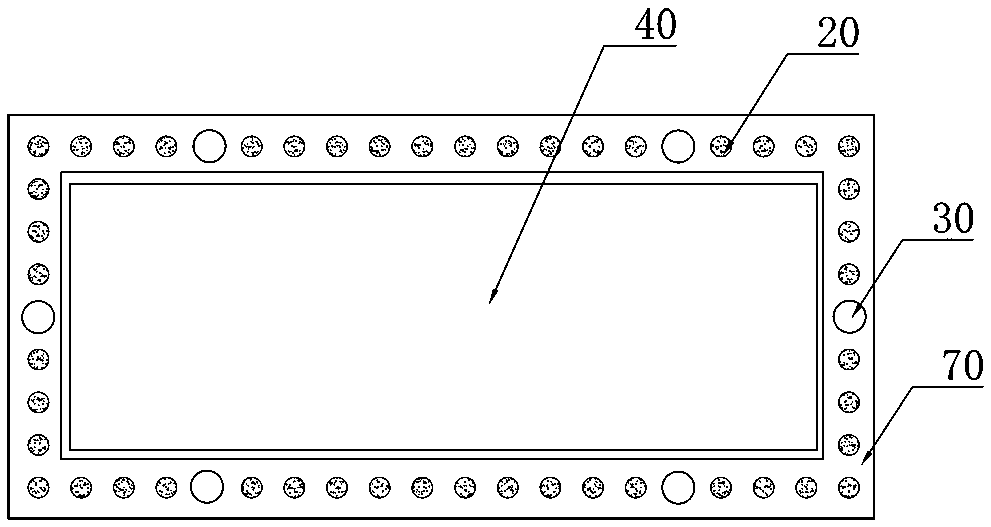
[0057] Such as figure 1 As shown, a horizontal sand well dewatering structure around the foundation pit includes several vertical sand wells 20 arranged at intervals around the foundation pit 40 and at least one horizontal sand well 70 arranged around the foundation pit 40. The horizontal sand wells 70 is located in the aquifer where the foundation pit 40 is located. The horizontal sand well 70 is connected to the vertical sand well 20. The horizontal sand well 70 is also connected to several vertical tube wells 30. Several vertical tube wells 30 are spaced around the foundation pit 40. Set, the vertical tube well 30 includes a water filtration section and a water storage section, and the water filtration section and the water storage section are arranged sequentially from top to bottom, and the dividing line between the water filtration section and the water storage section is located at the bottom of the lowest horizontal sand well 70 On the interface or below the bottom int...

Embodiment 2

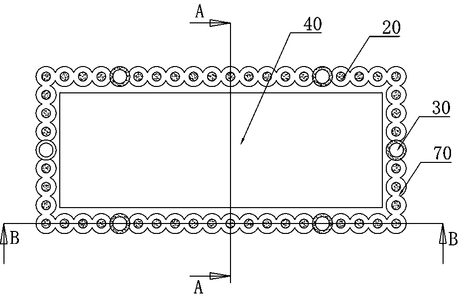
[0063] Based on the first embodiment, since the horizontal sand well 70 with a rectangular cross section is difficult and expensive in actual construction, in this embodiment, as Figure 3 to Figure 5 As shown, the horizontal sand well 70 includes several cylindrical sand columns 80 connected end to end in sequence and a retaining ring 60 located above the sand columns 80, there is a partial delivery between the adjacent sand columns 80, and the sand columns 80 and the vertical Set concentrically to the sand well 20. In the present embodiment, the sand column 80 is arranged concentrically with the vertical sand well 20, and when the vertical sand well 20 is drilled with a straight hole close to the horizontal sand well 70 position, the underwater soil expansion agitator is used to correct the horizontal sand well 70 position. The soil mass on the top is expanded, stirred and hardened to form retaining ring 60. The formed retaining ring 60 is umbrella-shaped, and then the soil ...

Embodiment 3

[0065] On the basis of the above examples, if Figure 3 ~ Figure 5 As shown, a method for dewatering and dewatering a horizontal sand well around a foundation pit comprises the following steps:

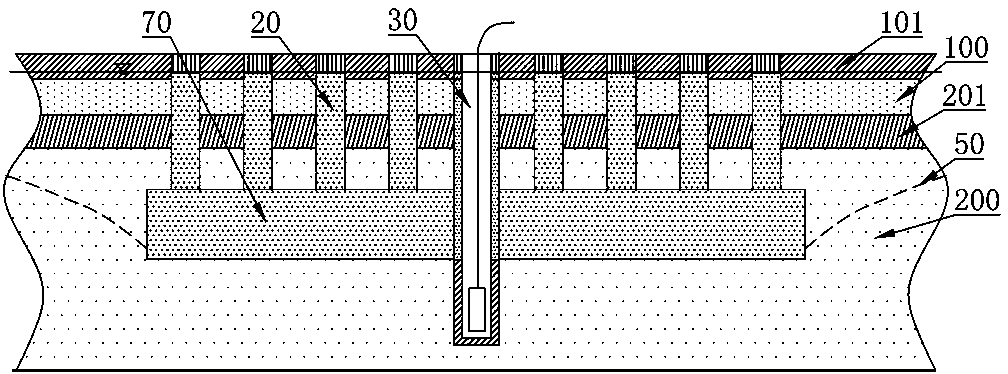
[0066] Step A. Determine the aquifer system according to the construction location of the foundation pit project, determine the thickness of each aquifer, the drawdown and the position of the lower aquifer, and judge the water content of each aquifer. In this embodiment, there are two in the scope of the foundation pit project Layer aquifers are the first aquifer 100 and the second aquifer 200. According to the basis that the deepest aquifer that has a harmful influence on foundation pit construction is the lower aquifer, it is judged that the second aquifer 200 is the lower aquifer;

[0067] Step B. Calculate the position and size of the horizontal sand well 70 located in the lower aquifer under the condition that the precipitation infiltration line in the foundation pit is 0.5m belo...


PUM


Abstract

The invention relates to a water-level-reducing and draining structure with horizontal sand wells around a foundation pit, and a water-level-reducing and draining method. The water-level-reducing anddraining structure with the horizontal sand wells around the foundation pit comprises a plurality of vertical sand wells arranged around the foundation pit at intervals, and the one or more horizontalsand wells arranged around the foundation pit, the horizontal sand wells are located in an aquifer where the foundation pit is located, the horizontal sand wells are connected with the vertical sandwells and further connected with a plurality of vertical tube wells, the vertical tube wells comprise water filtering sections and water storage sections, the boundary between the water filtering sections and the water storage sections is located on a bottom interface of the lowest horizontal sand well or is lower than the bottom interface of the lowest horizontal sand well, and the water storagesections are internally provided with water pumping equipment. When the purpose of water level reducing and draining of the foundation pit are achieved, the positions of bottom interfaces of the adopted horizontal sand well structures are very shallow, the depths of the bottom interfaces of the adopted horizontal sand well structures are far less than the depths of vertical well points, thus pumping of more irrelevant groundwater is avoided, and a series of problems caused by excessive pumping of the groundwater and deep groundwater can be relieved and even well solved.

Description

technical field [0001] The invention relates to the field of building construction, in particular to a dewatering and dewatering structure of a horizontal sand well around a foundation pit and a dewatering and dewatering method. Background technique [0002] The foundation pit dewatering mainly adopts the method of pumping water at vertical well points around the perimeter of the foundation pit to reduce the water level of the foundation pit. However, due to the depth of the funnel of the vertical well point dewatering, the depth of the well point is often required to reduce the water level of the foundation pit to the elevation required by the project. Very large, for example, the dewatering wells of foundation pits with a depth of 7-9m in a certain area are usually set up to 20-25m. For such a deep well point, the aquifer crossed is often multi-layered, and some aquifers in the lower part have negligible impact on the foundation pit, but the groundwater still needs to be p...

Claims


Application Information

Patent Timeline
IPC IPC(8): E02D19/06E02D19/10
CPCE02D19/06E02D19/10
Inventor 邹正盛郑清洁孙亚平王新宇王树仁王恒利顿志林秦莞臻
Owner HENAN POLYTECHNIC UNIV
Why Eureka
Try Eureka