Method for monitoring impurity injection amount in fusion device in real time

A technology of impurity injection and real-time monitoring, applied in the field of fusion, can solve problems such as inability to achieve real-time monitoring, influence of experimental results, difference between actual injection amount and table calibration value, etc., to meet the requirements of accurate measurement, reliable data support, and simple implementation. Effect

Inactive Publication Date: 2020-02-28
HEFEI INSTITUTES OF PHYSICAL SCIENCE - CHINESE ACAD OF SCI
View PDF5 Cites 1 Cited by
  • Summary
  • Abstract
  • Description
  • Claims
  • Application Information

AI Technical Summary

Problems solved by technology

However, traditionally, the amount of impurity implanted is based on the calibration data of the tabletop experiment, and the amount of impurity implanted in the plasma discharge environment cannot be monitored in real time.
In the specific discharge environment, due to the complex electromagnetic environment and the mechanical vibration of the injection system itself during discharge, there will be a huge difference between the real injection amount of impurities during discharge and the calibration value on the table, which will have a great impact on the subsequent experimental results. big impact

Method used


Image

  • Method for monitoring impurity injection amount in fusion device in real time
  • Method for monitoring impurity injection amount in fusion device in real time
  • Method for monitoring impurity injection amount in fusion device in real time

Examples


Embodiment Construction

[0020] The following will clearly and completely describe the technical solutions in the embodiments of the present invention with reference to the accompanying drawings in the embodiments of the present invention. Obviously, the described embodiments are only some, not all, embodiments of the present invention. The components of the embodiments of the invention generally described and illustrated in the figures herein may be arranged and designed in a variety of different configurations. Accordingly, the following detailed description of the embodiments of the invention provided in the accompanying drawings is not intended to limit the scope of the claimed invention, but merely represents selected embodiments of the invention. Based on the embodiments of the present invention, all other embodiments obtained by those skilled in the art without making creative efforts belong to the protection scope of the present invention.

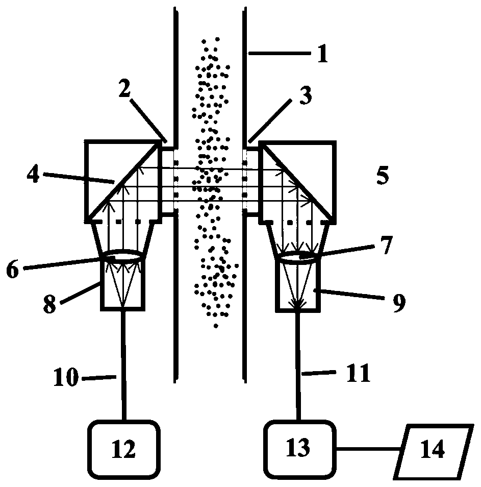
[0021] Such as figure 1 Shown is a method for real-...


PUM

PropertyMeasurementUnit
wavelengthaaaaaaaaaa
diameteraaaaaaaaaa
diameteraaaaaaaaaa

Abstract

The invention discloses a method for monitoring impurity injection amount in a fusion device in real time. The method comprises the following steps that: two opposite glass observation windows are mounted on two sides of an impurity injection pipeline, a laser generated by a laser emitter is emitted to an optical fiber, the other end of the optical fiber is connected with a metal tube provided with a convex lens, the laser penetrates through the convex lens and then is refracted into a beam of parallel light, the parallel light is reflected by a plane mirror, then penetrates through the two glass observation windows in a transmission mode and is reflected to another convex lens through the plane mirror, the parallel light enters the optical fiber after being converged by the convex lens and then is led into a laser receiver through the optical fiber, the laser receiver converts optical signals into electric signals, and the electric signals are collected in real time. In the fusion device, the laser emitter and the laser receiver are additionally arranged on the two sides of an impurity injection path according to the structure, and in the plasma discharge process, due to the factthat impurities can shield laser in the injection process, real-time monitoring of the impurity injection amount is achieved by monitoring and analyzing the intensity of the shielded laser. The optical path is simple, and reliable data support is provided for impurity injection research in a fusion experiment.

Description

technical field [0001] The invention relates to the field of fusion technology, in particular to a method for real-time monitoring of the injection amount of solid impurity powder in a fusion device. Background technique [0002] In recent years, the use of low-Z impurity implantation to control the radiation in the plasma divertor region, suppress the boundary localized modes (ELMs), and improve the plasma boundary recirculation has achieved fruitful experimental results. In these results, it is found that the amount of impurity implantation has a significant impact on many parameters of the plasma, such as boundary plasma energy storage, boundary temperature and so on. On this basis, the precise and quantitative study of the relationship between the amount of impurity implanted and the plasma parameters has attracted more and more attention of scientific researchers. Therefore, it is necessary to accurately measure the impurity injection amount under actual discharge cond...

Claims


Application Information

Patent Timeline
Patent Type & Authority Applications(China)
IPC IPC(8): G01F1/66
CPCG01F1/661G01F1/662
Inventor 钱玉忠孙震黄明徐伟孟献才李成龙韦俊庄会东左桂忠胡建生
Owner HEFEI INSTITUTES OF PHYSICAL SCIENCE - CHINESE ACAD OF SCI
Why Eureka
Try Eureka