Long-distance LC passive wireless sensing system

A passive wireless sensor system technology, applied in signal transmission systems, instruments, etc., can solve problems such as complex structure of the sensor system, achieve the goal of increasing the transmission distance, increasing the signal strength and Q value, and simplifying the structure of the sensor system Effect

Active Publication Date: 2020-02-28
SOUTHEAST UNIV
View PDF3 Cites 10 Cited by
  • Summary
  • Abstract
  • Description
  • Claims
  • Application Information

AI Technical Summary

Problems solved by technology

However, this technology needs to accurately calculate the critical value of strong magnetic coupling to avoid frequency splitting. At the same time, the relay coil makes the structure of the entire sensing system more complicated.

Method used


Image

  • Long-distance LC passive wireless sensing system
  • Long-distance LC passive wireless sensing system
  • Long-distance LC passive wireless sensing system

Examples


Embodiment 1

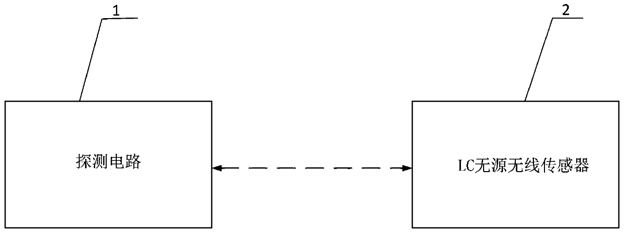
[0026] Example 1. The structural block diagram of a kind of remote LC passive wireless sensing system that the present invention proposes is as follows figure 1 As shown, the long-distance LC passive wireless sensor system includes: a detection circuit 1 and an LC passive wireless sensor circuit 2; the detection circuit 1 and the LC passive wireless sensor circuit 2 are wirelessly connected through inductive magnetic resonance weak coupling.

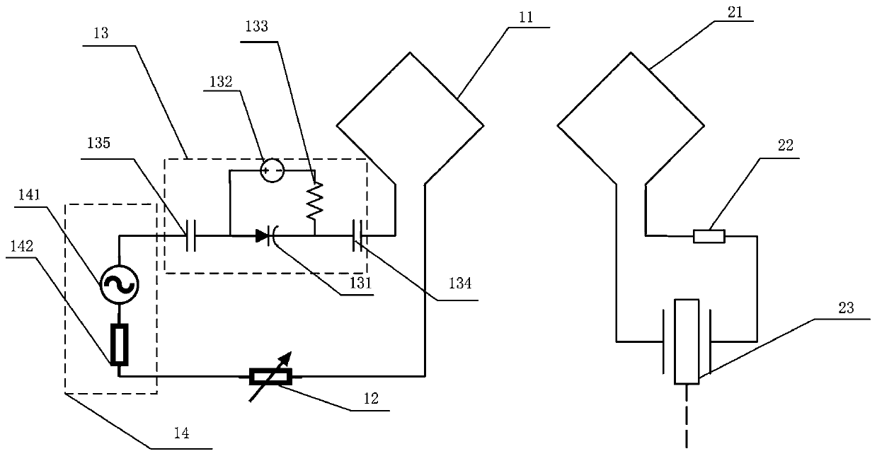
[0027] The equivalent circuit of a long-distance LC passive wireless sensing system proposed by the present invention is as follows figure 2 As shown, the detection circuit 1 includes: a first inductance coil 11 , an adjustable resistor 12 , an adjustable capacitor module 13 and a vector network analysis module 14 . One end of the first inductance coil 11 is connected with one end of the adjustable resistor 12, the other end of the adjustable resistor 12 is connected with one end of the vector network analysis module 14, and the other ...

Embodiment 2

[0031] Example 2. In order to avoid frequency splitting between the detection circuit and the LC passive wireless sensor circuit and affect the long-distance transmission of passive wireless signals, the present invention proposes to optimize the design of the capacitance, inductance and resistance values ​​of the detection circuit and the LC passive wireless sensor circuit .

[0032] In the first design scheme, each circuit parameter in the detection circuit 1 and the LC passive wireless sensor 2 satisfies the following relationship:

[0033] (1) The inductance value of the first inductance coil 11 is identical with the inductance value of the second inductance coil 21;

[0034] (2) The capacitance value of the adjustable capacitor module 13 is equal to the capacitance value of the sensitive capacitor 23:

[0035] (3) The resistance value of the detection circuit 1 is equal to the inverse of the resistance value of the load or circuit parasitic resistance 23 .

[0036] Whe...

Embodiment 3

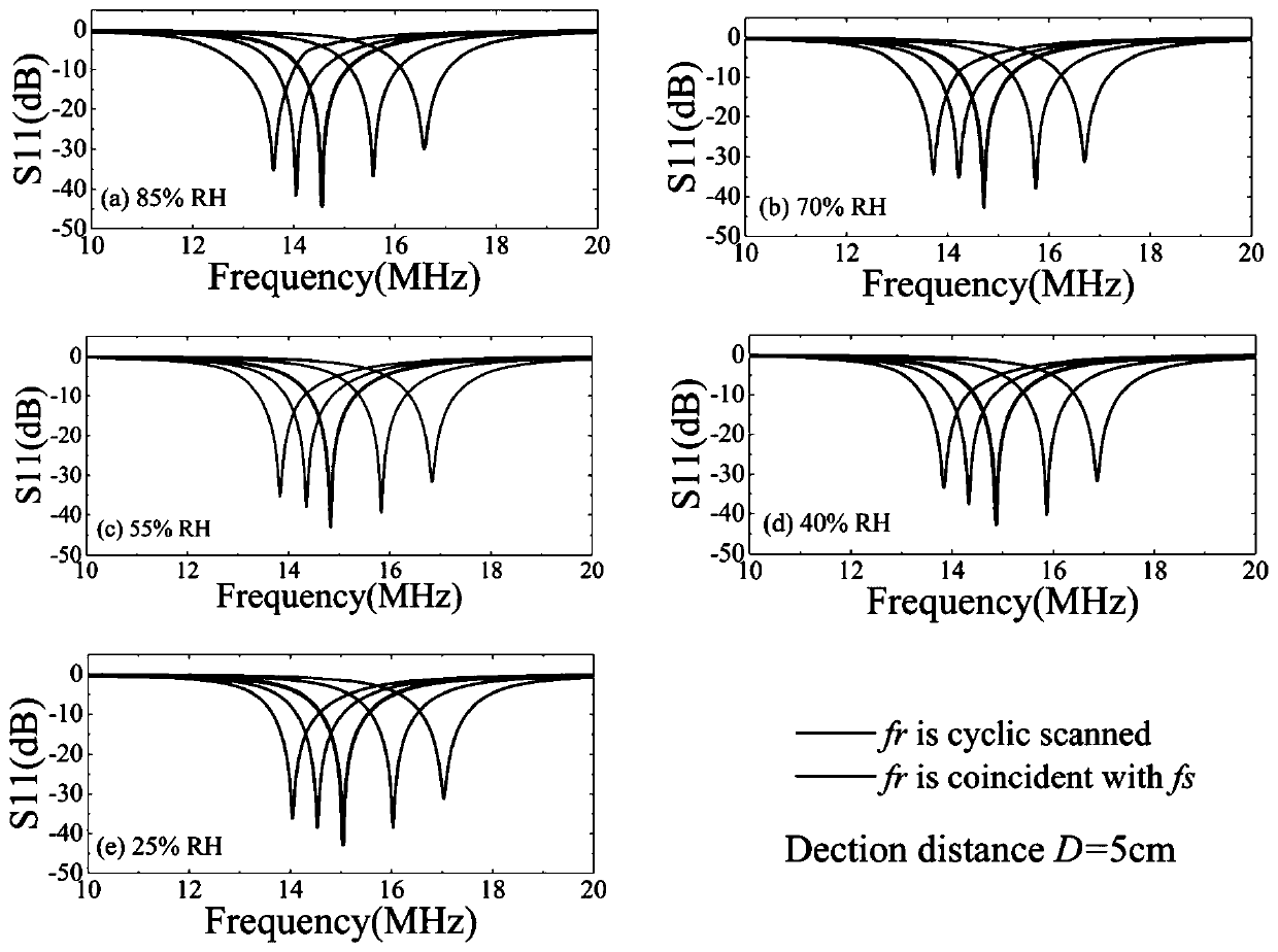
[0044] Example 3. In this preferred embodiment, the long-distance LC passive wireless sensing system based on the PT symmetry breaking area is tested with an LC type humidity sensor. As the ambient humidity changes, the resonant frequency of the humidity sensor changes. Using the detection circuit proposed by the present invention, a series of response curves S11 under 5 different humidity points are tested at the detection distance D=5cm, as image 3 shown. image 3 Among them, fs is the resonant frequency of the humidity sensor to be tested, and fr is the resonant frequency of the detection circuit. Adjust fr to perform cyclic scanning, and obtain 5 S11 curves at each humidity point. When fr=fs, that is, the sensing system resonates, and the S11 signal measured by the vector network analysis module 14 is the strongest at this time, so the frequency corresponding to the strongest signal curve is the resonance frequency of the currently detected LC humidity sensor. The detec...


PUM


Abstract

The invention provides a long-distance LC passive wireless sensing system, and relates to the technical field of wireless passive sensing systems. In the system, a detection circuit is wirelessly connected with an LC passive wireless sensor circuit through inductive magnetic resonance weak coupling. By designing the capacitance values, the inductance values and the resistance values of the detection circuit and the LC passive wireless sensor circuit, the resonance frequencies of the detection circuit and the LC passive wireless sensor circuit are equal, the gain and the loss of the system arealso equal, and therefore, the PT symmetry or PTX symmetry is met. According to the LC passive wireless sensing system provided by the invention, the frequency splitting can be avoided, and passive wireless signal enhancement and ultra-long-distance transmission are realized. The capacitance value of the detection circuit is adjustable, so the inherent frequency of the detection circuit can be consistent with the signal frequency of the sensor circuit all the time, thereby achieving the efficient transmission of full-frequency signals. An adjustable resistor is added in the detection circuit,so the signal intensity and the Q value are greatly improved. The sensing system circuit structure design satisfying PTX symmetry has more flexible requirements for inductance and capacitance.

Description

technical field [0001] The invention relates to the technical field of wireless passive sensing systems, in particular to a long-distance LC passive wireless sensing system. Background technique [0002] In more and more fields, LC passive wireless sensors have been widely used to monitor physical, chemical and biological parameters of the environment. The advantages are: first, no wired connection, suitable for moving or rotating objects, inside the human body and harsh environments; second, passive characteristics, small size and long life. However, its own small size makes the readout distance of traditional methods very limited. In the prior art, there are three ways of wireless sensing: one is the radiation type, the transmission distance is longer, but the transmission efficiency of the omnidirectional antenna is particularly low, and the unidirectional radiation requires uninterrupted line of sight and complex tracking devices; the other is One is the electromagneti...

Claims


Application Information

Patent Timeline
Patent Type & Authority Applications(China)
IPC IPC(8): G08C17/02G08C17/04
CPCG08C17/02G08C17/04
Inventor 周彬彬王立峰董蕾黄庆安
Owner SOUTHEAST UNIV
Why Eureka
Try Eureka