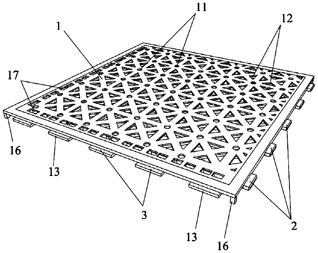
Splicing floor tile

A floor tile and body technology, applied in the direction of floors, buildings, adhesives, etc., can solve the problems of high construction difficulty, poor surface flatness, long construction time, etc. The effect of facilitating subsequent maintenance and replacement

Pending Publication Date: 2020-03-06
上海品宅装饰科技有限公司
View PDF0 Cites 3 Cited by
  • Summary
  • Abstract
  • Description
  • Claims
  • Application Information

AI Technical Summary

Problems solved by technology

[0003] The existing floor tile paving methods have the following disadvantages: due to the use of cement mortar for paving, the construction is difficult, such as the mix ratio of cement mortar, water immersion before floor tile construction, leveling of pavement height and other processes, the construction time is long, and materials are wasted Many, high labor costs, improper operation, prone to heat expansion and contraction, drumming and cracking, in the subsequent replacement, it is necessary to use a cutting machine to remove the bad floor tiles, the efficiency is low, and the effect is poor; the connection between the floor tiles The difference in seam height is obvious, the surface flatness is poor, and the floor tiles are prone to problems such as hollowing and warping; the thickness of cement mortar for traditional floor tiles plus the thickness of the floor tiles itself reduces the indoor clear height space

Method used


Image

  • Splicing floor tile
  • Splicing floor tile
  • Splicing floor tile

Examples


Embodiment Construction

[0028] In order to make the technical problems solved by the present invention, the technical solutions adopted and the technical effects achieved clearer, the technical solutions of the embodiments of the present invention will be further described in detail below in conjunction with the accompanying drawings. Obviously, the described embodiments are only the technical solutions of the present invention. Some, but not all, embodiments. Based on the embodiments of the present invention, all other embodiments obtained by those skilled in the art without creative efforts fall within the protection scope of the present invention.

[0029] In the description of the present invention, it should be noted that the terms "center", "upper", "lower", "left", "right", "vertical", "horizontal", "inner", "outer" etc. The indicated orientation or positional relationship is based on the orientation or positional relationship shown in the drawings, and is only for the convenience of describin...


PUM


Abstract

The invention relates to the field of building decoration, and discloses a splicing floor tile. The splicing floor tile comprises a floor tile body, a splicing protrusion and a splicing groove, wherein a vent hole and an adhesive overflow groove are formed in the floor tile body, the splicing groove and the splicing protrusion are arranged on the side surface of the floor tile body, and the splicing protrusion of one splicing floor tile can horizontally extend into a splicing groove of another splicing floor tile. According to the splicing floor tile, the vent hole is capable of releasing bubbles generated when an adhesive is applied, the adhesive overflow groove is capable of extruding excess adhesive out from the position between the floor tile body and a bonding layer, the excess adhesive can be bonded with the inner wall of the adhesive overflow groove, the bonding area is expanded, the traditional complicated procedures such as leveling and troweling are omitted, the paving efficiency is high, the construction time is short, the surface flatness is good, the paving quality is easy to guarantee, subsequent maintenance and replacement are facilitated, the material cost and the labor cost are saved, thick cement mortar layers are omitted, and indoor net height space is expanded.

Description

technical field [0001] The invention relates to the field of architectural decoration, in particular to a mosaic floor tile. Background technique [0002] Floor tile is a kind of ground decoration material, which is mostly used for the ground and floor of public buildings and civil buildings. The existing way of paving floor tiles is usually: use cement mortar to pave the floor tiles to the ground. During the paving process, it is necessary to tap with a rubber hammer to ensure the adhesion of the floor tiles and mortar, avoid hollowing in the later stage, and wait for paving After the mortar is solidified, the joints of the floor tiles are jointed with powdered joints. [0003] The existing floor tile paving methods have the following disadvantages: due to the use of cement mortar for paving, the construction is difficult, such as the mix ratio of cement mortar, water immersion before floor tile construction, leveling of pavement height and other processes, the constructio...

Claims


Application Information

Patent Timeline
Patent Type & Authority Applications(China)
IPC IPC(8): E04F15/02
CPCE04F15/02038E04F15/0215
Inventor 马红军张准杨懿铭
Owner 上海品宅装饰科技有限公司
Why Eureka
Try Eureka