Device for improving signal to noise ratio of inductosyn signal

A technology of inductive synchronizer and signal-to-noise ratio, which is applied in the direction of using electrical devices, measuring devices, and amplifiers with only semiconductor devices, etc., which can solve the problem of serious pre-amplifier interference, difficulty in obtaining angle measurement data, and increased high-order harmonic components and other problems to achieve high accuracy, filter out electromagnetic interference, and eliminate angle measurement errors

Active Publication Date: 2020-03-06
武汉华之洋科技有限公司
View PDF7 Cites 5 Cited by
  • Summary
  • Abstract
  • Description
  • Claims
  • Application Information

AI Technical Summary

Problems solved by technology

[0004] When the induction synchronizer is used in the turntable and swing table, the induction synchronizer is usually installed at the shaft end of the turntable and swing table, and the distance from the motor is relatively close. PulseWidthModulation, wide pulse) modulation current is easy to interfere with the ferrite porcelain tank of the induction synchronizer through electromagnetic induction, resulting in sine and cosine waveform distortion, increasing high-order harmonic components, resulting in random errors in angle measurement, resulting in low angle measurement accuracy, At present, it is mainly by setting a protective layer on the induction synchronizer or improving the quality of the motor to avoid magnetic flux leakage. However, since the PWM modulation current must exist when the motor is running, especially when the motor accelerates, the interference to the preamplifier is more serious. , it is even difficult to obtain more accurate angle measurement data

Method used


Image

  • Device for improving signal to noise ratio of inductosyn signal
  • Device for improving signal to noise ratio of inductosyn signal
  • Device for improving signal to noise ratio of inductosyn signal

Examples


Embodiment Construction

[0026] Embodiments of the present invention will be described in further detail below in conjunction with the accompanying drawings.

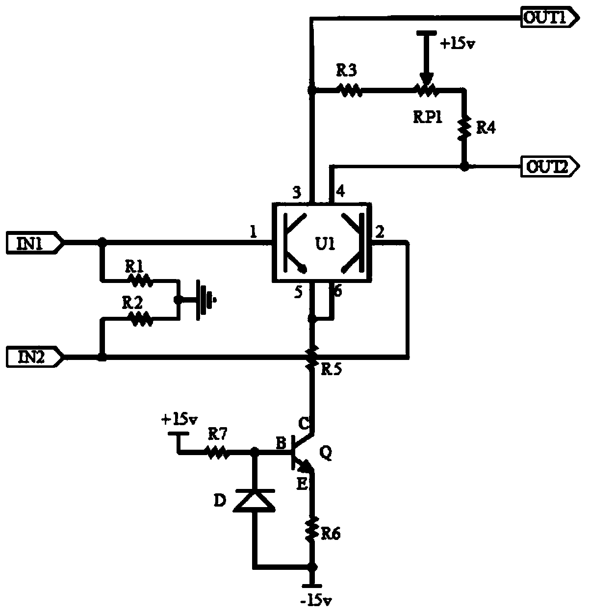
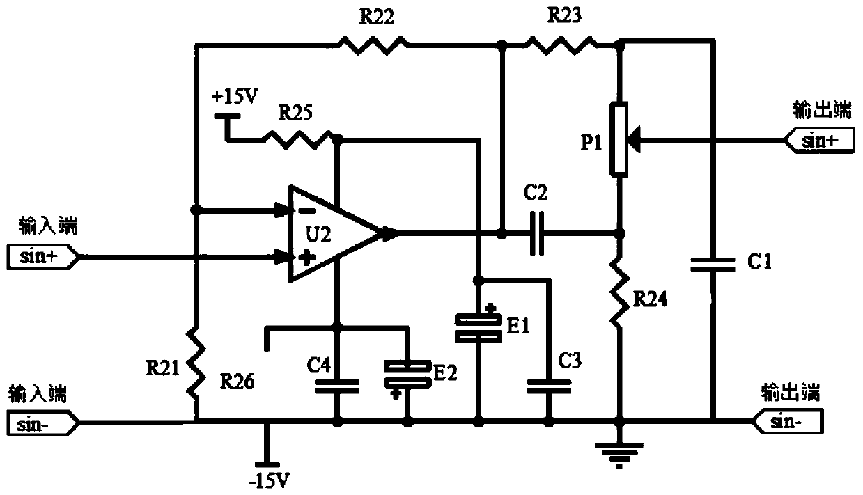
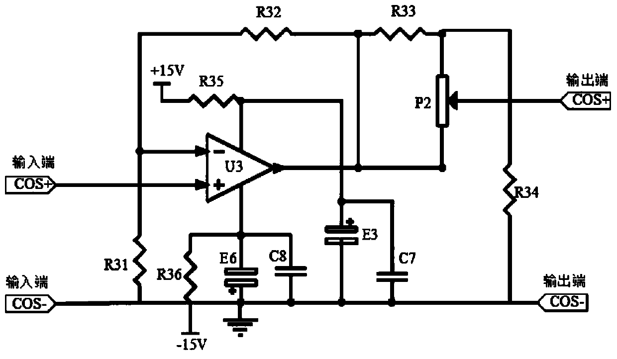
[0027] The present invention adopts a high-precision matching tube and a constant current source circuit to form a pre-amplifier, performs pre-amplification on the output signal of the inductive synchronizer, and uses a high-precision operational amplifier as the second-stage amplifier to perform sine and cosine signals on the inductive synchronizer. Two-stage amplification, and the quadrature adjustment circuit is designed in the sine two-stage amplifier, and the amplitude adjustment circuit is designed in the cosine two-stage amplifier.

[0028] see figure 1 As shown, the embodiment of the present invention provides a device for improving the signal-to-noise ratio of the inductive synchronizer signal, including a preamplifier circuit, a sine secondary amplifying circuit and a cosine secondary amplifying circuit, and the preamplifying circuit ...


PUM


Abstract

The invention discloses a device for improving the signal to noise ratio of an inductosyn signal, and relates to the field of inductosyn angle measurement. The device comprises a pre-amplification circuit, the pre-amplification circuit comprises a signal input terminal IN1, a signal input terminal IN2, a high-precision matching tube U1, a triode Q and a diode D, the signal input terminal IN1 and the signal input terminal IN2 are connected with an output winding of an inductosyn, the resistors R3 and R4 are connected with a potentiometer RP1 in series to form a zero adjustment circuit, and thetriode Q, the diode D, a resistor R5, a resistor R6 and a resistor R7 form a constant current source circuit. A pre-amplifier adopts the high-precision matching tube to carry out amplification processing, the background noise of the inductosyn and the electromagnetic interference generated by motor PWM can be effectively filtered by utilizing the characteristic of high matching parameters of the high-precision matching tube, and a zero voltage can be adjusted by an adjusting potentiometer RP1 in the pre-amplification circuit, so that the influence of zero error is eliminated.

Description

technical field [0001] The invention relates to the field of angle measurement of an inductive synchronizer, in particular to a device for improving the signal-to-noise ratio of an inductive synchronizer. Background technique [0002] The rotary inductive synchronizer is usually used to measure the angular displacement of the system. In order to amplify the induction signal in the inductive synchronizer to the amplitude that meets the resolution requirements of the solving circuit, it is usually necessary to set up a preamplifier, and the preamplifier can also perform sine and cosine The phase and amplitude adjustment of the signal can ensure the consistency and orthogonality of the sine and cosine channel signals. [0003] A traditional inductosynchronizer usually uses a ferrite pot and an operational amplifier set up in sequence as a preamplifier. First, the ferrite pot is used for the first-stage signal amplification, and then the operational amplifier is used for the sec...

Claims


Application Information

Patent Timeline
Patent Type & Authority Applications(China)
IPC IPC(8): G01B7/30H03F3/10
CPCG01B7/30H03F3/10
Inventor 佘江元晏明全张绪清陈平安黄萍
Owner 武汉华之洋科技有限公司
Why Eureka
Try Eureka