Single-beacon passive acoustic positioning method for underwater glider under the influence of ocean currents
An underwater glider and acoustic positioning technology, applied in satellite radio beacon positioning systems, positioning, radio wave measurement systems, etc., can solve problems such as performance degradation, position estimation failure, failure, etc., to improve positioning performance and improve positioning performance , implementing simple effects
- Summary
- Abstract
- Description
- Claims
- Application Information
AI Technical Summary
Problems solved by technology
Method used
Image
Examples
Embodiment 1
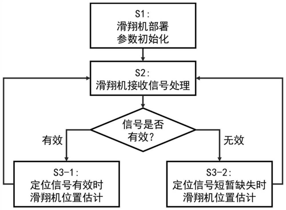
[0065] The flow of a method for passive acoustic positioning of an underwater glider under the influence of ocean currents provided by an embodiment of the present invention is as follows: figure 1 shown. The glider locates itself according to the time-of-arrival difference of the received positioning signal and the signal angle of arrival (Direction Of Arrival, DOA). The method includes the following steps.
[0066] Step S1: Glider deployment, parameter initialization step
[0067] After the glider is deployed, it corrects its position on the sea surface through GPS. After the glider starts underwater navigation, it continues to monitor the signal to determine whether it has received a positioning signal. At initialization, the ocean current velocity can be calculated without prior knowledge of the ocean current The initial value is set to [0 0], if there is prior knowledge, the ocean current velocity The initial value is set to the corresponding value. The error cova...
Embodiment 2
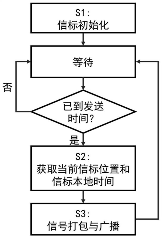
[0112] The embodiment of the present invention provides a process for sending beacon positioning signals, such as figure 2 shown. In the embodiment, the beacon periodically broadcasts positioning signals, and the beacon can be carried on any surface or underwater platform, such as surface ships, drilling platforms, buoys, wave gliders, UUVs, submarines, etc. The method includes the following steps:
[0113] Step S1: Beacon initialization step
[0114] After the beacon is deployed, it will set the sending cycle of the positioning signal Signal bandwidth and other parameters, and enter the waiting to send stage.
[0115] Step S2: Get the current beacon position and beacon sending time step
[0116] At the time the signal is sent, the beacon will get the current position of the beacon and beacon sending time
[0117] Step S3: Signal packaging and broadcasting
[0118] The beacon position and beacon time obtained in step S2 of the CAN signal with good autocorrelation a...
Embodiment 3
[0120] The positioning signal frame structure provided by the embodiment of the present invention, such as Figure 5 shown. The signal frame consists of a CAN signal with good autocorrelation and the beacon position at the time of transmission and sending time constitute.
[0121] The above-mentioned products can execute the methods provided by the embodiments of the present invention, and have corresponding functional modules and beneficial effects for executing the methods. For technical details that are not exhaustively described in this embodiment, refer to the method provided in the embodiment of the present invention.
PUM
 Abstract
Description
Claims
Application Information
 - R&D
- Intellectual Property
- Life Sciences
- Materials
- Tech Scout
- Unparalleled Data Quality
- Higher Quality Content
- 60% Fewer Hallucinations
Browse by: Latest US Patents, China's latest patents, Technical Efficacy Thesaurus, Application Domain, Technology Topic, Popular Technical Reports.
© 2025 PatSnap. All rights reserved.Legal|Privacy policy|Modern Slavery Act Transparency Statement|Sitemap|About US| Contact US: help@patsnap.com


