Tool track interpolation and speed planning method based on machine tool vibration suppression

A technology of vibration suppression and tool trajectory, applied in the field of CNC machining

Active Publication Date: 2020-03-06
INST OF MACHINERY MFG TECH CHINA ACAD OF ENG PHYSICS
View PDF8 Cites 13 Cited by
  • Summary
  • Abstract
  • Description
  • Claims
  • Application Information

AI Technical Summary

Problems solved by technology

Overall, existing trajectory smoothing and velocity planning methods are still deficient in suppressing machine tool vibrations

Method used


Image

  • Tool track interpolation and speed planning method based on machine tool vibration suppression
  • Tool track interpolation and speed planning method based on machine tool vibration suppression
  • Tool track interpolation and speed planning method based on machine tool vibration suppression

Examples


Embodiment 1

[0173] In this embodiment, a tool trajectory interpolation and speed planning method based on machine tool vibration suppression is described, and the specific steps are as follows:

[0174] (1) Step 1, read the G01 track point into the memory of the numerical control system.

[0175] (2) Step 2, for the G01 trajectory segment obtained in step 1, design G that satisfies the chord error constraint 4 Continuous interpolation trajectory, the specific operation method is as follows:

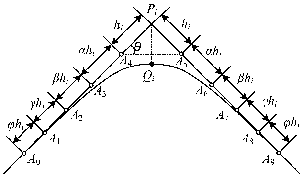
[0176] Step 2-1, establish G at the corner of the G01 trajectory 4 Geometric Model of Continuous Transition Curves

[0177] Trajectory corner P i-1 P i P i+1 The transition curve at is composed of symmetrical nine-degree Bezier curves, such as figure 1 As shown, the mathematical form of the transition curve is shown in formula 1:

[0178]

[0179] In formula (1) A i represents a control point that satisfies where α, β, γ, is the control point ratio (CPR), and the value of the contr...

Embodiment 2

[0308] Based on a tool trajectory interpolation and speed planning method based on machine tool vibration suppression provided in Embodiment 1, specific application cases are shown in the following three links:

[0309] (1) The trajectory point of the "dolphin" model {P i} i=0…219 Read into the memory of the CNC system, the G01 track point of the model is as follows Figure 6 shown;

[0310] (2) Read the G01 trajectory segment from the memory {P i} i=0…219 , design G that satisfies the chordal error constraint 4 Continuously interpolated trajectories. Let the chord error constraint of the trajectory be δ=0.04mm, and the calculation accuracy be ε=10 -4 mm, use the algorithm InterG4 provided in steps 2-4 to calculate the G of the "dolphin" model 4 Continuous interpolation trajectory, the trajectory curve generated by 4 iterations is recorded as: Determine {P according to formula (2) i (4)} The CPR value at each corner of the sequence, calculated according to the CPR v...


PUM


Abstract

The invention discloses a tool track interpolation and speed planning method based on machine tool vibration suppression. The method comprises the steps of 1, reading a G01 track point into a numerical control system memory; 2, aiming at a G01 track segment obtained in the step 1, designing a G4 continuous interpolation track meeting a chord error constraint; and 3, designing a speed curve calculation method with smooth acceleration and time optimal under two known conditions for the smooth track obtained in the step 2, and giving a speed planning method under the dynamic performance constraint of each axis of motion. The track generated by the method meets the chord error constraint strictly and can allow the G01 point to pass through, and compared with a G2 corner transition track and aG3 interpolation track, the curvature extreme value at the corner can be further reduced, the speed fluctuation at the corner is relieved, and the impact of the machine tool is reduced. The designed speed planning method can ensure the machining efficiency and improve the vibration suppression level of the machine tool, thereby providing an important means for the development of a numerical control system interpolator of high-speed and high-precision machining.

Description

technical field [0001] The invention relates to the technical field of numerical control machining, in particular to a tool trajectory interpolation and speed planning method based on machine tool vibration suppression. Background technique [0002] The tool path continuity and feed speed planning methods in the CNC system are the key links to realize high-precision and high-stability machining. The tool trajectory generated by the computer-aided manufacturing (CAM) system is a piecewise linear trajectory with only G 0 Continuously, the mechanism tends to generate large vibrations at the corners of the machining track, which affects the quality of the machined surface. In order to reduce the impact of the machine tool during processing and improve the surface quality of the workpiece, it should be ensured that the tool path has G k (k≥2) continuity. The tool trajectory with high-order geometric continuity helps to improve the smoothness of the trajectory and the speed lim...

Claims


Application Information

Patent Timeline
Patent Type & Authority Applications(China)
IPC IPC(8): G05B19/416
CPCG05B19/4166G05B2219/43001G05B2219/49078
Inventor 樊炜刘晓卓黄文韩文杰武芃樾吴定柱
Owner INST OF MACHINERY MFG TECH CHINA ACAD OF ENG PHYSICS
Why Eureka
Try Eureka