Conveyor belt upper contour trajectory tracking control system and method

A trajectory tracking and control method technology, applied in the field of robotics, can solve the problems of low automation level, the workpiece can not meet the process requirements, and can not meet the high precision requirements, so as to improve the defects of the machined parts, improve the trajectory following accuracy, and realize the trajectory The effect of dynamic follow

Pending Publication Date: 2020-03-06
QUANZHOU HUAZHONG UNIV OF SCI & TECH INST OF MFG +1
View PDF5 Cites 2 Cited by
  • Summary
  • Abstract
  • Description
  • Claims
  • Application Information

AI Technical Summary

Problems solved by technology

[0002] At present, my country's manufacturing industry is still in the stage of low automation level. During the production process, the conveyor belt must be stopped in each process, and the workpiece is processed by manpower or robots in a static environment. The production efficiency is low and cannot meet many high-precision requirements.
[0003] At present, most of the industrial contour processing technology is completed on a fixed platform, which is determined by th

Method used


Image

  • Conveyor belt upper contour trajectory tracking control system and method
  • Conveyor belt upper contour trajectory tracking control system and method
  • Conveyor belt upper contour trajectory tracking control system and method

Examples


Embodiment 1

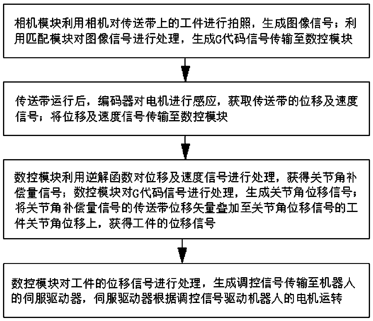
[0044] Such as figure 1 As shown, a contour trajectory tracking control method on a conveyor belt includes the following steps:

[0045] Step 1. The camera module 1 uses the camera to take pictures of the workpiece on the conveyor belt to generate an image signal; uses the matching module 2 to process the image signal, obtains the G code signal and transmits it to the numerical control module 4;

[0046] Step 2. After the conveyor belt runs, the encoder 3 senses the motor 6 to obtain the displacement and speed signals of the conveyor belt; the displacement and speed signals are transmitted to the numerical control module 4;

[0047] Step 3. The numerical control module 4 uses the inverse solution function to process the displacement and speed signals to obtain the joint angle compensation signal; the numerical control module 4 processes the G code signal to generate the joint angle displacement signal; the conveyor belt displacement of the joint angle compensation signal The ...

Embodiment 2

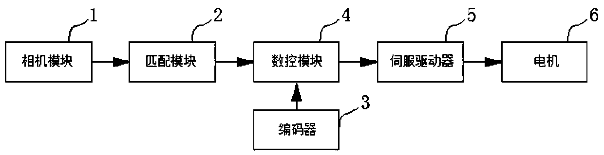
[0067] Such as image 3 As shown, a contour trajectory tracking control system on a conveyor belt includes:

[0068] A camera module 1, the camera module 1 uses a camera to take pictures of the workpiece on the conveyor belt to generate an image signal;

[0069] A matching module 2, the matching module 2 processes the image signal, acquires a G code signal and transmits it to the numerical control module 4;

[0070] Encoder 3, described encoder 3 senses motor 6 after conveyor belt runs, and obtains the displacement and speed signal of conveyor belt;

[0071] Numerical control module 4, described numerical control module 4 utilizes the inverse solution function to process displacement and speed signal, obtains the joint angle compensation amount signal; Numerical control module 4 processes G code signal, generates joint angle displacement signal; Joint angle compensation amount signal The displacement vector of the conveyor belt is superimposed on the joint angular displaceme...


PUM


Abstract

The invention relates to a conveyor belt upper contour trajectory tracking control method. The method comprises the steps that a camera module photographs a workpiece on a conveyor belt to generate animage signal; the image signal is processed by a matching module to generate a G code signal; the encoder senses a motor to acquire displacement and speed signals of the conveying belt; the displacement and speed signals are transmitted to a numerical control module; the numerical control module processes the displacement and speed signals by using an inverse solution function to acquire a jointangle compensation amount signal; the numerical control module processes the G code signal to generate a joint angle displacement signal; the joint angle compensation amount signal and the joint angledisplacement signal are processed to acquire a displacement signal of the workpiece; the numerical control system generates a control signal according to the displacement signal of the workpiece andtransmits the control signal to a servo driver; and the servo driver drives the motor to rotate. According to the invention, dynamic track following can be achieved; the calculation speed is increased; and the trajectory following precision is improved.

Description

technical field [0001] The present invention relates to the technical field of robots, in particular to a tracking control system and method for a contour track on a conveyor belt of a six-joint robot. Background technique [0002] At present, my country's manufacturing industry is still in the stage of low automation level. During the production process, the conveyor belt must be stopped in each process, and the workpiece is processed by manpower or robots in a static environment. The production efficiency is low and cannot meet many high-precision requirements. . [0003] At present, most of the industrial contour processing technology is completed on a fixed platform, which is determined by the high precision and stability of the contour processing itself, but it is precisely because of this characteristic that the production efficiency Under some special process requirements, if the contour processing cannot be followed dynamically and in real time, the workpiece will ...

Claims


Application Information

Patent Timeline
IPC IPC(8): G05D1/12
CPCG05D1/12
Inventor 连志军张雪俊张锴王平江徐慧陈曼林洪亮
Owner QUANZHOU HUAZHONG UNIV OF SCI & TECH INST OF MFG
Why Eureka
Try Eureka