
Liquid metal cooling reactor based on increase of fuel utilization rate and management method

A liquid metal cooling and utilization rate technology, applied in the field of nuclear reactors, can solve the problems of large neutron leakage in liquid metal cooling fast reactors, reduce fuel utilization, and affect core fuel economy, etc., to improve average unloading and reduce loading The effect of increasing the quantity and enhancing the realizability of the project

Active Publication Date: 2020-03-06
NUCLEAR POWER INSTITUTE OF CHINA
View PDF11 Cites 4 Cited by
  • Summary
  • Abstract
  • Description
  • Claims
  • Application Information

AI Technical Summary

Problems solved by technology

In order to meet the safety requirements, liquid metal reactors usually use strong neutron-absorbing stainless steel as the cladding material, which affects the fuel economy of the core.
At the same time, the neutron leakage of the liquid metal cooling fast reactor is large, which will also reduce the fuel utilization rate
The above reasons lead to a large gap between the proliferation capacity of the closed uranium-plutonium cycle nuclear fuel of metal fast reactors compared with the theoretical value. Therefore, it is very necessary to explore a liquid metal cooling fast reactor core design method with a higher nuclear fuel utilization rate, and to improve the nuclear fuel capacity. Breeding Capability, Enhanced Engineering Realization of Closed Uranium-Plutonium Nuclear Fuel Cycle Systems

Method used


Image

  • Liquid metal cooling reactor based on increase of fuel utilization rate and management method
  • Liquid metal cooling reactor based on increase of fuel utilization rate and management method
  • Liquid metal cooling reactor based on increase of fuel utilization rate and management method

Examples


Embodiment 1

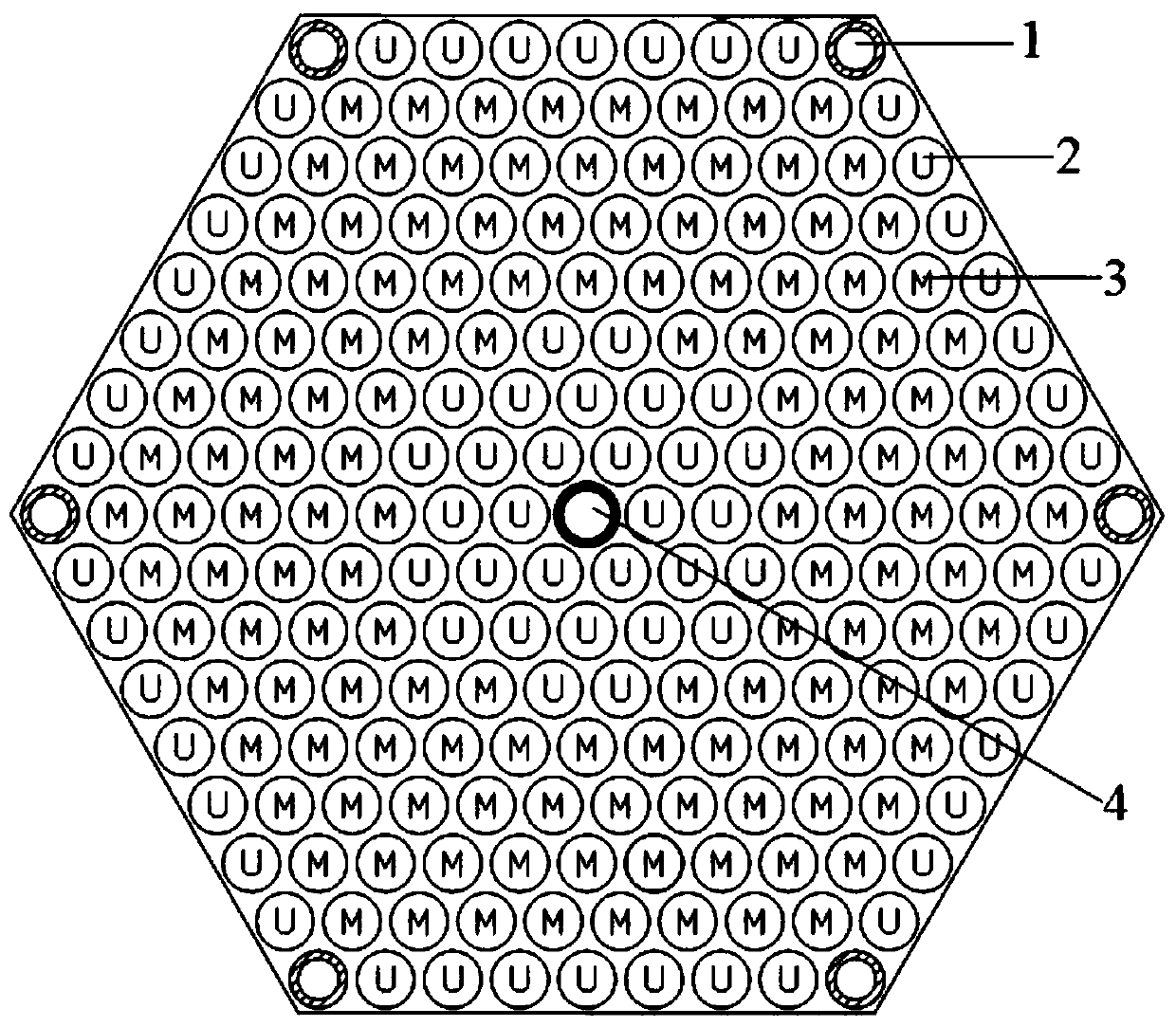
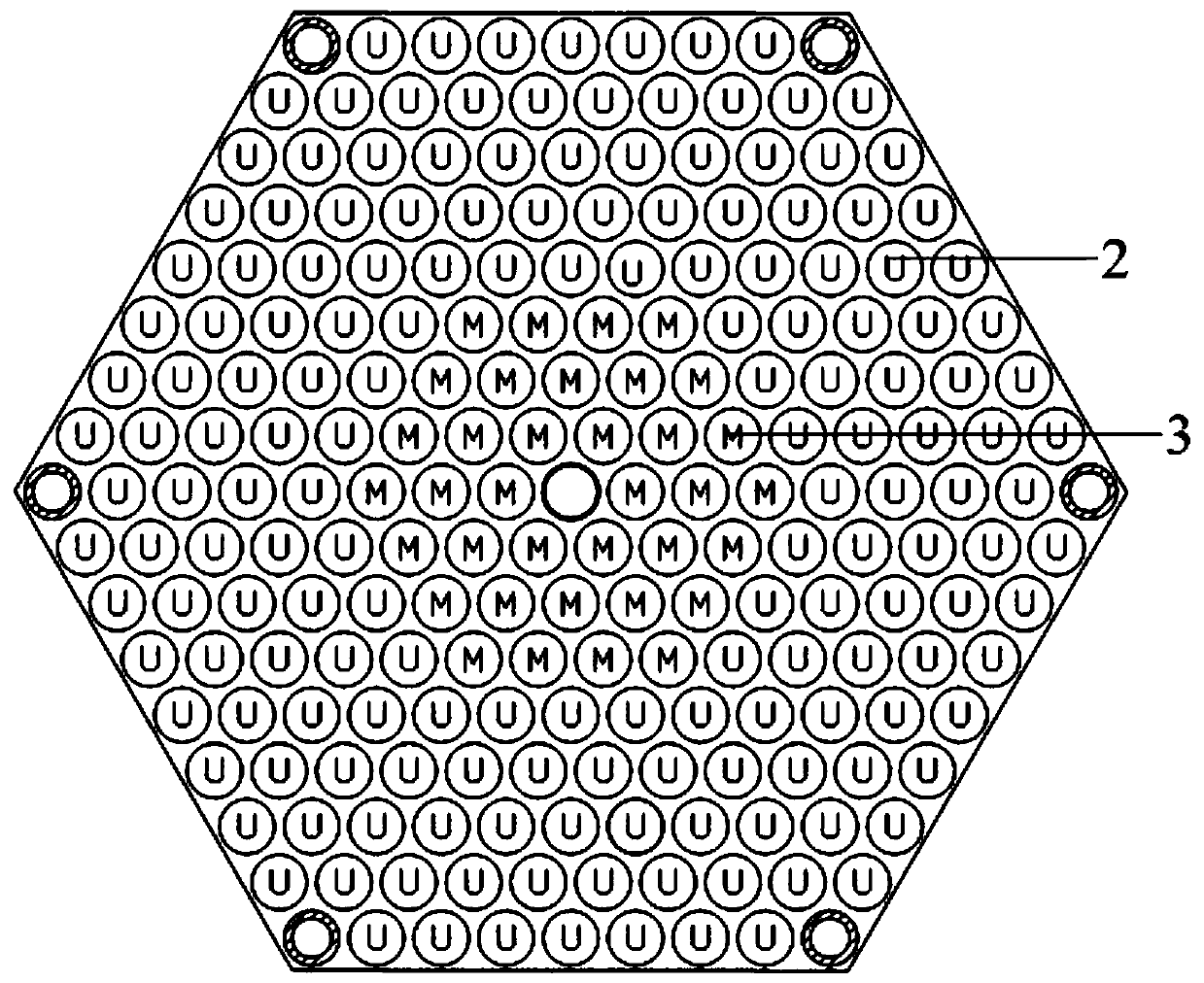
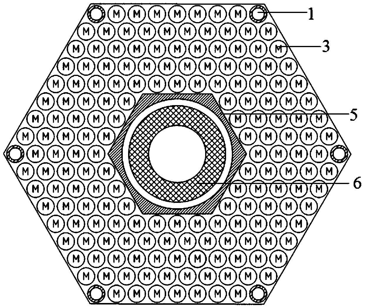
[0027] Such as Figure 1 to Figure 4 As shown, based on the liquid metal cooling reactor with improved fuel utilization rate, a circle of low-power fuel assemblies 7 is arranged on the outermost periphery of the reactor core, and control rod assemblies 9 and high-power fuel assemblies 8 are arranged crosswise in the inner area of ​​the core. Both the low-power fuel assembly 7 and the high-power fuel assembly 8 are hexagonal fuel assemblies composed of a positioning tube 1, an instrument tube 4, a natural uranium dioxide fuel rod element 2 and a uranium-plutonium oxide fuel rod element 3; The natural uranium dioxide fuel rod element 2 is arranged in two circles in the power fuel assembly 7, the uranium plutonium oxide fuel rod element 3 is arranged between the two circles of natural uranium dioxide fuel rod elements 2, and the high power fuel assembly 8 is natural The uranium dioxide fuel rod element 2 is arranged in a circle, and the uranium plutonium oxide fuel rod element 3 ...


PUM


Abstract

The invention discloses a liquid metal cooling reactor based on increase of a fuel utilization rate and a management method. A low-temperature intensive moderating component is arranged at the periphery of a reactor core of the reactor; a high-temperature intensive moderating component is arranged at a secondary periphery; and high-power control rod components and high-power intensive moderating components are alternatively arranged in an inner area of the reactor core. According to characteristics of inherent neutronic properties, power and burnup distribution of a liquid metal cooling fast reactor, components of different functions and purposes are constructed, namely a lower-power fuel component which is used at the outermost periphery of the reactor core and used for reducing neutron leakage, and a high-power fuel component and a control rod component which are used inside the reactor core, a unique liquid metal cooling fast reactor core loading scheme is formed, the average unloading burnup and the nuclear fuel conversion rate of the liquid metal cooling fast reactor are remarkably increased, and the engineering realizability of a closed uranium-plutonium fuel cycle system ofthe liquid metal cooling fast reactor is improved.

Description

technical field [0001] The invention relates to the technical field of nuclear reactors, in particular to a liquid metal cooling reactor and a management method based on improving fuel utilization. Background technique [0002] Liquid metal-cooled reactors using a closed uranium-plutonium fuel cycle system have great development potential in nuclear waste transmutation and nuclear fuel proliferation, such as sodium-cooled fast reactor (SFR), lead (bismuth) cooled fast reactor (LFR), etc. It is of great significance to the sustainable development of nuclear fuel. In addition, the liquid metal cooling reactor also has high safety and economy, so it has become the main reactor type of the IV generation advanced nuclear energy system. Because liquid metal has no neutron moderation ability, the loading of highly enriched uranium plutonium oxide fuel or uranium dioxide fuel in the core is relatively high. In order to meet the safety requirements, liquid metal reactors usually us...

Claims


Application Information

Patent Timeline
IPC IPC(8): G21C5/12G21C19/20
CPCG21C5/12G21C19/205Y02E30/30
Inventor 夏榜样孙伟严明宇余红星柴晓明李松蔚李文杰
Owner NUCLEAR POWER INSTITUTE OF CHINA
Learn More