Wick structure and heat pipe accommodating wick structure

A liquid-absorbing core and structure technology, which is applied in the direction of heat exchanger tubes, indirect heat exchangers, heat exchange equipment, etc., can solve the problem of not being able to sufficiently reduce the fin spacing of the suction part, not being able to obtain capillary force, and the complexity of the shape of the flow path etc. to achieve excellent heat transfer characteristics, improved thermal conductivity, and improved capillary force

Active Publication Date: 2020-03-06
FURUKAWA ELECTRIC CO LTD
View PDF12 Cites 0 Cited by
  • Summary
  • Abstract
  • Description
  • Claims
  • Application Information

AI Technical Summary

Problems solved by technology

However, when the surface area is increased in order to increase the capillary force, there is a problem that the pressure loss when the working fluid flows through the wick structure increases.
[0005] However, in the heat pipe of Patent Document 1 provided with a wave-shaped suction portion having folded fins, there is a problem that the fin pitch of the suction portion cannot be sufficiently reduced, and sufficient capillary force cannot be obtained.
In addition, in the heat pipe of Patent Document 1, there is also the following problem: because the shape of the suction portion such as the wave shape, that is, the portion of the suction portion in the direction perpendicular to the longitudinal direction of the case is not opened, when the heat pipe from the liquid When the working fluid whose phase changes to the gas phase flows through the suction part, it suffers pressure loss
However, in the sintered body of metal powder and the metal mesh, there is a problem that although it is easy to obtain a predetermined capillary force, when the working fluid from the liquid phase to the gas phase flows through the sintered body of the metal powder or the metal mesh, Due to the complexity of the shape of the flow path, there may be pressure loss

Method used


Image

  • Wick structure and heat pipe accommodating wick structure
  • Wick structure and heat pipe accommodating wick structure
  • Wick structure and heat pipe accommodating wick structure

Examples


Embodiment Construction

[0048] Hereinafter, the liquid-absorbent wick structure of the first embodiment of the present invention and the heat pipe housing the liquid-absorbent wick structure of the first embodiment will be described with reference to the drawings. First, the heat pipe in which the liquid-absorbent wick structure is housed will be described.

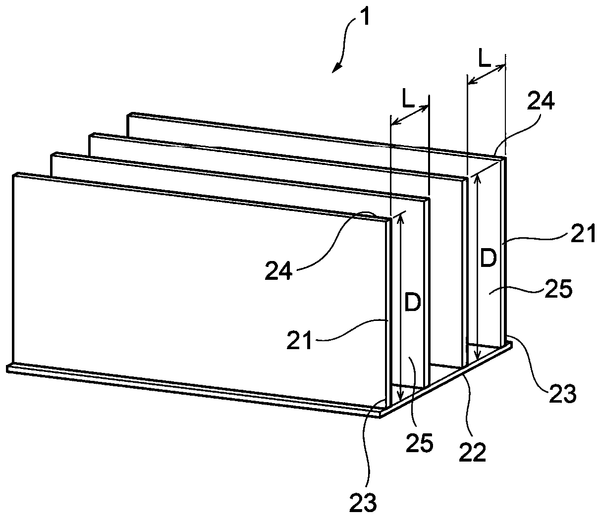
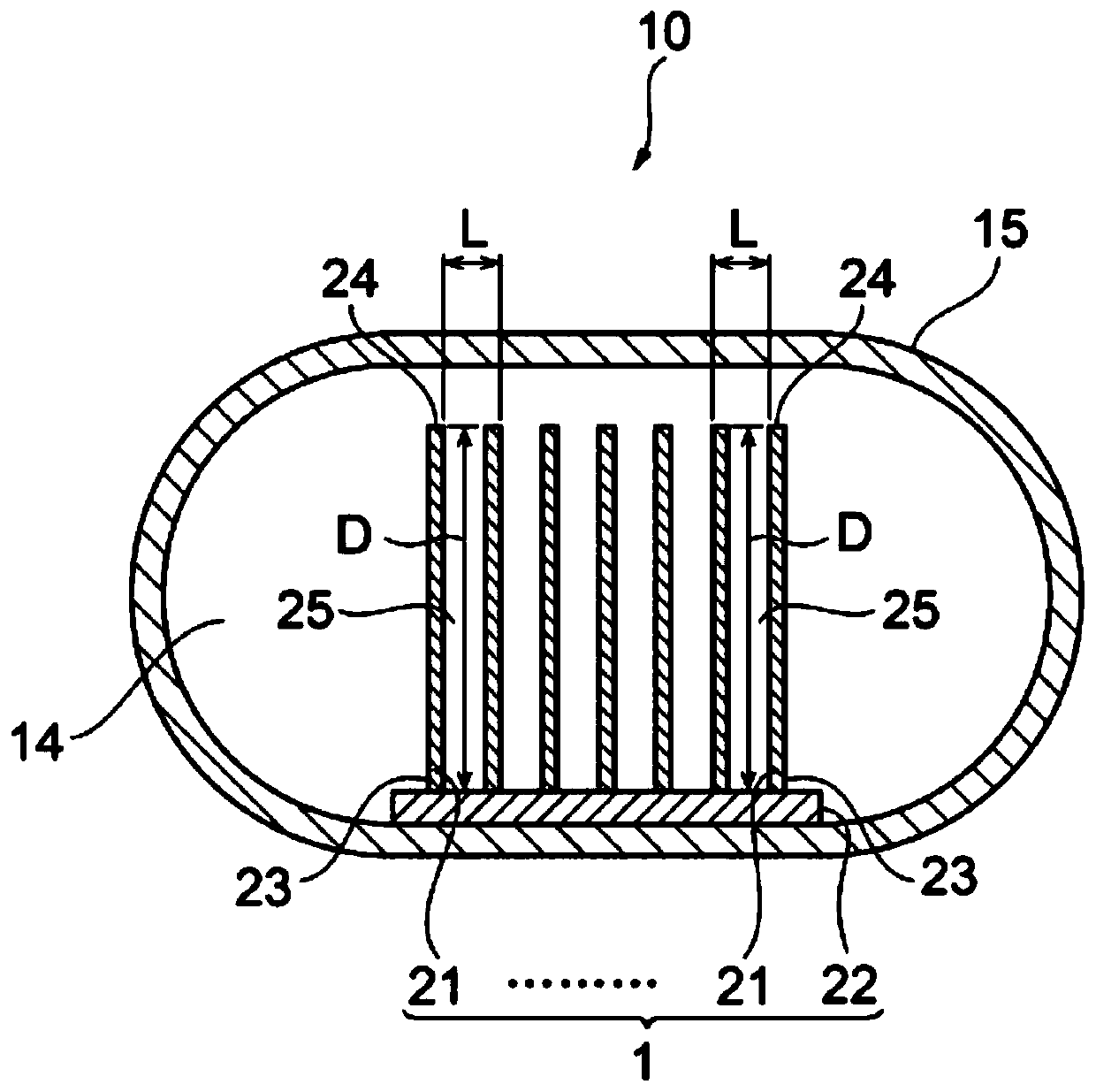
[0049] Such as image 3 , 7As shown, the liquid-absorbent wick structure 1 of the first embodiment is housed inside the container 15 of the heat pipe 10 . The container 15 is a tubular member. A working fluid (not shown) is sealed inside the container 15 .

[0050] Container 15 is a closed tube. The cross-sectional shape in the direction perpendicular to the longitudinal direction of the container 15 is not particularly limited, but in the heat pipe 10, it has a flat shape. In addition, the shape of the container 15 in the longitudinal direction is not particularly limited, but in the heat pipe 10, it is substantially linear.

[0051] The ...


PUM

PropertyMeasurementUnit
Arithmetic mean roughnessaaaaaaaaaa
Thicknessaaaaaaaaaa

Abstract

Provided are: a wick structure that can reduce pressure loss of an operating fluid that is circulating, without loss of capillary force; and a heat pipe that, by accommodating the wick structure, exhibits outstanding heat transport properties. This wick structure is accommodated in the interior of a container of the heat pipe and includes a plurality of pieces of foil that are erected so as to face one another.

Description

technical field [0001] The present invention relates to a liquid-absorbent wick structure capable of reducing the pressure loss of a working fluid, and a heat pipe exhibiting excellent heat transfer characteristics by accommodating the liquid-absorbent wick structure. Background technique [0002] Electronic components such as semiconductor elements mounted in electric and electronic equipment generate more heat due to high-density mounting with higher functionality, and cooling becomes even more important. As a cooling method for electronic components, a method using a heat pipe is included. [0003] As described above, since the calorific value of the heat generating body increases, it is required to further improve the heat transfer characteristics of the heat pipe. In order to further improve the heat transfer characteristics, a scheme of reducing the pressure loss when the working fluid encapsulated in the heat pipe circulates in the liquid-absorbent wick structure is ...

Claims


Application Information

Patent Timeline
IPC IPC(8): F28D15/04F28F21/02F28F21/04F28F21/08
CPCF28D15/046F28F3/06F28D15/0233F28F3/048F28F3/12F28F2210/10
Inventor 海渕朋未虎谷智明
Owner FURUKAWA ELECTRIC CO LTD
Why Eureka
Try Eureka