Profile control and displacement control method and device for fireflood well group

A fire-flooding well group and control-flooding technology, which is used in earth-moving drilling, wellbore/well components, and production fluids, etc., can solve the problems of ineffective production of injected gas, fast gas propulsion, and uneven suction, avoiding the The effect of "fingering" and gas channeling, increasing the swept area and reducing the passing capacity

Pending Publication Date: 2022-06-07
PETROCHINA CO LTD
View PDF0 Cites 0 Cited by
  • Summary
  • Abstract
  • Description
  • Claims
  • Application Information

AI Technical Summary

Problems solved by technology

[0004] Due to the differences in porosity and permeability in the vertical and horizontal planes of general reservoirs, the problems of uneven gas absorption in the vertical direction and gas channeling in the plane appear in the process of continuous combustion accelerant, that is, continuous gas injection. Gas overburden occurs on the top of the formation, and gas channeling occurs in the production wells at the high part of the formation, and the gas advances rapidly in the direction with good physical properties on the plane, and the fire flooding front advances rapidly in this direction, causing the problem of fire channeling. After this problem occurs, it leads to A large amount of injected gas quickly breaks through to some production wells, affecting the normal production of the production wells, resulting in ineffective recovery of the injected gas, and at the same time, the problem of uneven vertical and horizontal production occurs, which affects the oil displacement efficiency and ultimate recovery factor
[0005] At present, in order to solve the problem of fire channeling, profile control and plugging agents are usually added to the fire flooding well group. However, since the temperature near the fire flooding front of the fire flooding well group is as high as 700-800°C, the temperature It is also as high as 300-400°C, and the temperature resistance of profile control and plugging agent does not exceed 300°C, making it difficult to realize its profile control and flooding effect

Method used


Image

  • Profile control and displacement control method and device for fireflood well group
  • Profile control and displacement control method and device for fireflood well group
  • Profile control and displacement control method and device for fireflood well group

Examples


Embodiment 1

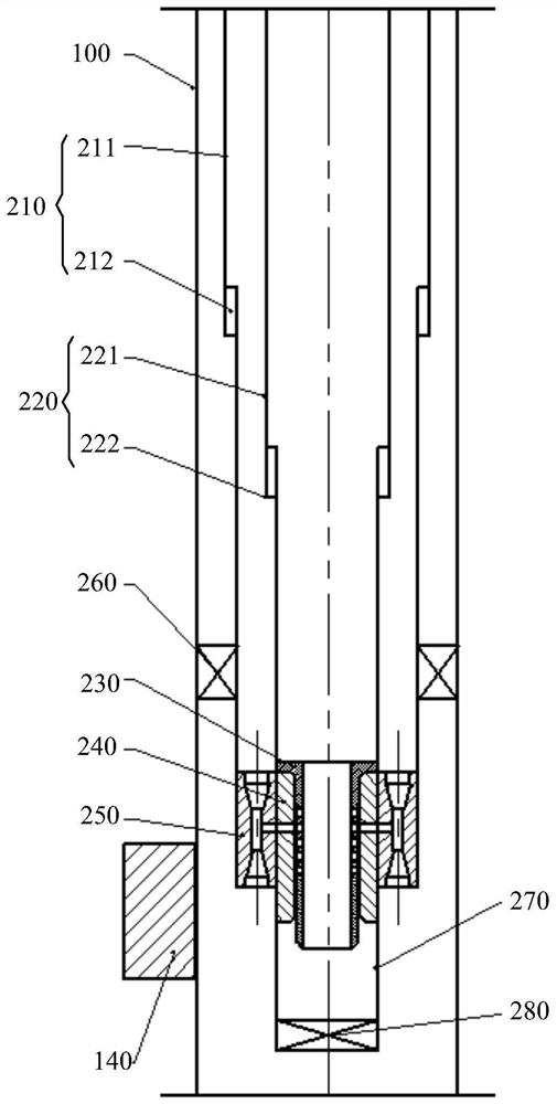
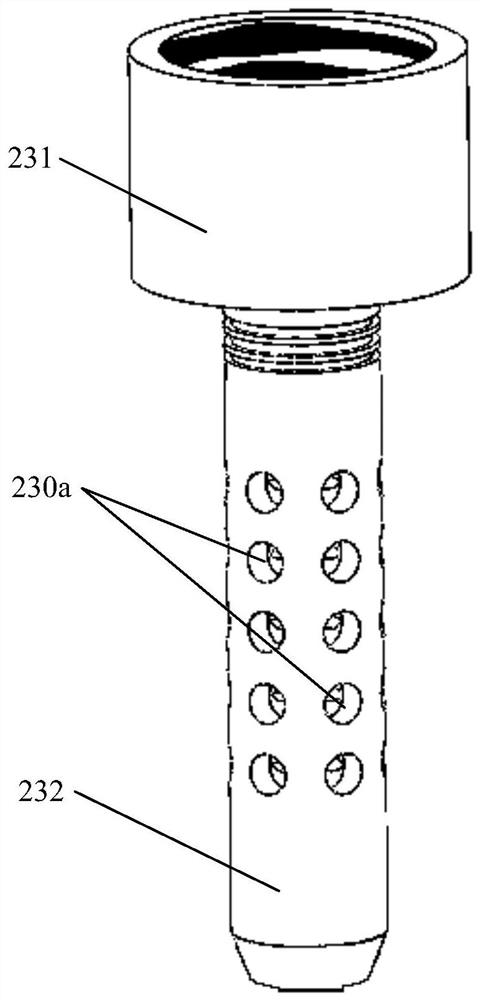
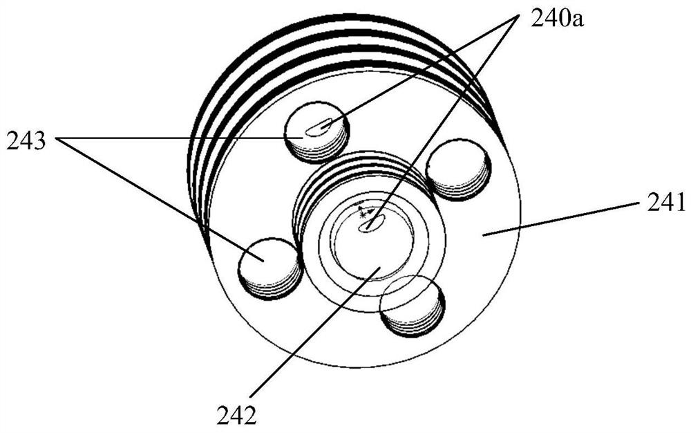
[0042] figure 1 A schematic structural diagram of the profile control and drive device provided in Embodiment 1; figure 2 A schematic structural diagram of the insertion tube in the profile control and drive device provided in Embodiment 1; image 3 It is a schematic structural diagram of the atomizer in the profile control and drive control device provided in Embodiment 1; Figure 4 A schematic structural diagram of the jet tube in the profile control and drive device provided in Embodiment 1; Figure 5 It is a schematic diagram of the change of the front and rear longitudinal upper live lines during the process of profile control and driving measures; Image 6 This is a schematic diagram of the change of the live line on the front and rear planes in the process of profile control and flood control (taking the reverse nine-spot well pattern as an example).

[0043] Among them, L1 represents the longitudinal advance of the live wire before profile control and drive; D1 rep...

Embodiment 2

[0081] This embodiment provides a method for profile control and drive based on the profile control and drive device in the first embodiment, including:

[0082] injecting gas into the annular space between the outer tube 210 and the inner tube 220, so that the gas enters the jet tube 250;

[0083] The liquid is injected into the inner tube 220, so that the liquid enters the jet tube 250 through the insertion tube 230 and the atomizer 240, and the gas and liquid entering the jet tube 250 are mixed to form aerosol and ejected from the jet tube 250, so that the gas The fog can be injected into the formation to produce the effect of profile control and flooding.

[0084] The production process based on the aforementioned profile control and drive device will be explained below. The production process includes: going down stage, ignition stage, normal gas injection stage, profile control and flooding stage.

[0085] In the downhole stage, the aforementioned profile control and d...


PUM


Abstract

The invention provides a profile control and displacement control method and device for a fireflood well group, and the method comprises the steps: injecting gas into an annular space between an outer pipe and an inner pipe to enable the gas to enter a jet pipe when the fireflood well group has the sign of gas channeling or non-uniform effect, and injecting liquid into the inner pipe to enable the gas to enter the jet pipe; the liquid enters the jet pipe through the insertion pipe and the atomizer, and the gas and the liquid entering the jet pipe are mixed to form aerial fog to be sprayed out from the jet pipe; after sprayed aerial fog is injected into an original gas channeling channel, the capillary force can be improved, the fluid passing capacity can be reduced, follow-up injected gas is forced to turn, and an air suction adjusting section is formed in the longitudinal direction of a near-wellbore zone to achieve profile control; when the aerial fog is close to a fireflooding front edge high-temperature area, tiny water drops in the aerial fog are vaporized into steam, and the steam and air are mixed to form mixed gas, so that the mobility ratio between a displacement medium and a displaced formation fluid can be reduced, the oil displacement efficiency can be improved, the swept area can be increased, and profile control and displacement can be realized.

Description

technical field [0001] The invention relates to the technical field of petroleum exploitation, in particular to a profile control and drive method and a device for fire drive well groups. Background technique [0002] Fire flooding, also known as fire oil layer, refers to an oil recovery method in which the temperature of the oil layer reaches the ignition point of crude oil by means of electricity and chemistry, and air or oxygen is injected into the oil layer to make the oil in the oil layer continue to burn; oil wells based on fire flooding are called fire flooding. well drive group. [0003] The fire-flooding well group includes injection wells and production wells; among them, a fire-flooding injection string is set in the injection well, and air or oxygen-enriched gas is continuously injected into the injection well through the fire-flood injection string as a combustion-supporting agent, and methods such as spontaneous combustion and artificial ignition are adopted. ...

Claims


Application Information

Patent Timeline
Patent Type & Authority Applications(China)
IPC IPC(8): E21B43/243E21B43/24
CPCE21B43/243E21B43/24E21B43/166
Inventor 冯光陈军任永苍史智峰费涛袁建波王磊田文静梁晗周明旺阎逸超
Owner PETROCHINA CO LTD
Why Eureka
Try Eureka