Concrete processing equipment adopting annular stirring

A kind of processing equipment and concrete technology, which is applied in the field of concrete processing equipment with circular agitation, can solve the problems of affecting the construction progress, slow mixing efficiency of raw materials, uneven mixing, etc., and achieve the effect of shortening the mixing time, improving the mixing effect and mixing evenly

Inactive Publication Date: 2020-03-13
曹元国
View PDF8 Cites 2 Cited by
  • Summary
  • Abstract
  • Description
  • Claims
  • Application Information

AI Technical Summary

Problems solved by technology

[0003] The existing concrete processing equipment is to put concrete raw materials into the mixing tank, and the internal mixing mechanism is driven by the motor to rotate to mix the raw materials. This kind of mixing method is single, the mixing efficiency of raw materials is slow, and the mixing is not uniform enough. It is easy to form a mixing dead angle inside, and it takes a lot of time to mix, which affects the construction progress. Therefore, it is necessary to improve the existing concrete processing equipment

Method used


Image

  • Concrete processing equipment adopting annular stirring
  • Concrete processing equipment adopting annular stirring
  • Concrete processing equipment adopting annular stirring

Examples


Embodiment 1

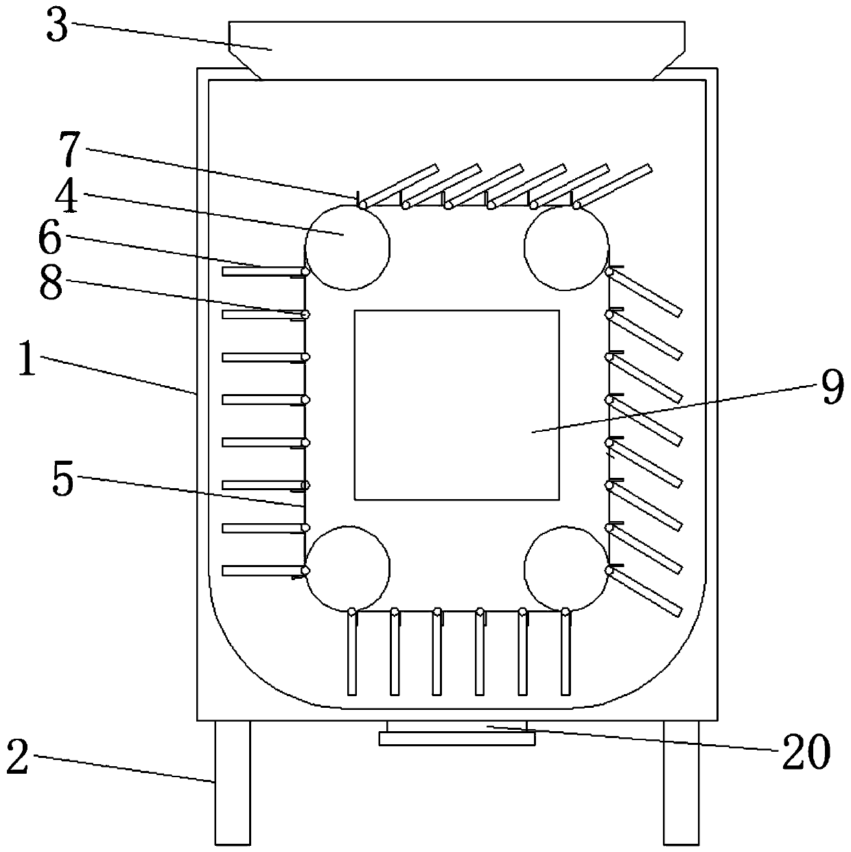
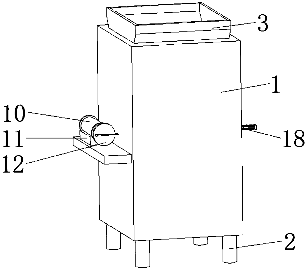
[0023] Please refer to the figure, in the embodiment of the present invention, a kind of annular stirring concrete processing equipment includes a mixing tank 1, a leg 2, a feed hopper 3 and a discharge port 20; the four corners of the bottom of the mixing tank 1 are fixed supports Leg 2 supports the mixing tank 1 through the supporting leg 2, and a shock-absorbing foot is fixedly installed on the lower end of the supporting leg 2, which plays a shock-absorbing role during mixing and reduces noise; the feeding hopper 3 is fixed on the top of the mixing tank 1 And it communicates with the inside, the raw materials are sent into the mixing tank 1 through the feed hopper 3, and the bottom of the mixing tank 1 is connected with a discharge port 20 with an end cover, and the mixed concrete is discharged from the discharge port 20.

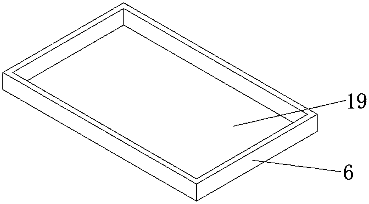
[0024] The mixing tank 1 is provided with four driving rollers 4 in the water direction, and the four driving rollers 4 are respectively located on the ...

Embodiment 2

[0027] On the basis of embodiment 1, in order to avoid the dead angle of stirring, a reciprocating stirring piece 9 moving back and forth is arranged inside the rectangle surrounded by the driving belt 5, and the area of ​​the reciprocating stirring piece 9 accounts for 2 / 3-3 of the inner area of ​​the driving belt 5 / 4, occupies most of the space in the driving belt 5, and the concrete therein is moved by the reciprocating stirring piece 9 moving back and forth; Going out from the side wall of the mixing tank 1, one end is fixedly connected with several return springs 18, and the other end of the return spring 18 is fixedly connected on the outer wall of the mixing tank 1, and the push-pull rod 17 is supported by the return spring 18, so that the push-pull rod 17 is Can be reset after pulling, is convenient to the reciprocating movement of push-pull rod 17; On the other end of push-pull rod 17, is connected with connecting rod 15 by rotating shaft 16 rotations, pulls push-pull...


PUM


Abstract

The invention relates to the field of concrete processing, and particularly discloses concrete processing equipment adopting annular stirring. The concrete processing equipment comprises a stirring tank, supporting legs, a feeding hopper and a discharging outlet; four driving rollers in the horizontal directions are arranged in the stirring tank and located on the four corners correspondingly, andthe four driving rollers are located at the bottom and the upper part of the stirring tank correspondingly and arranged in a left-right symmetrical mode; a driving band is wound around the four driving rollers and forms a rectangular ringlike structure; and a plurality of pushing plates are rotatably connected to the outer side wall of the driving band through fixedly-mounted hinges and evenly distributed on the driving band at equal distances. According to the concrete processing equipment, the rectangular driving band is arranged in the stirring tank and located at the upper part and the bottom, and the stirring range of the concrete processing equipment is expanded; and the multiple pushing plates are rotatably mounted on the outer side of the driving band, in the moving process of thedriving band, internal concrete raw materials move through the pushing plates, and thus the internal raw materials are stirred.

Description

technical field [0001] The invention relates to the field of concrete processing, in particular to an annular stirring concrete processing equipment. Background technique [0002] Concrete is a general term for engineering composite materials in which aggregates are cemented into a whole by cementitious materials. Generally speaking, the term concrete refers to the cement concrete obtained by using cement as the cementitious material, sand and stone as the aggregate; mixed with water (may contain admixtures and admixtures) in a certain proportion, and stirred. Concrete, which is widely used in civil engineering. Concrete processing equipment is a mechanical equipment that uses machines to replace manual mixing of cement, river sand, gravel, and water according to a certain mix ratio to produce concrete required for production operations such as construction projects. Commonly used equipment includes concrete pump trucks, Cement silo, batching station, etc. [0003] The ex...

Claims


Application Information

Patent Timeline
Patent Type & Authority Applications(China)
IPC IPC(8): B28C5/08B28C5/14B28C7/16
CPCB28C5/08B28C5/14B28C7/16
Inventor 曹元国
Owner 曹元国
Why Eureka
Try Eureka